Most Arduino boards do not produce a true continuous analogue voltage. Instead, they use Pulse Width Modulation (PWM) to simulate analogue signals by rapidly toggling a digital pin between 0V and 5V. To achieve a "true" smooth analogue output, you must use a board with a built-in Digital-to-Analog Converter (DAC) or add an external RC filter or DAC module.
Defining Analogue Output in the Arduino Ecosystem
In the context of 2026 electronics design, the term "analogue output" on an Arduino often leads to confusion for beginners. While we think of an analogue signal as a smooth, continuous wave—like a dimmer switch or a volume knob—microcontrollers are fundamentally digital devices. They operate using binary states: HIGH (typically 5V or 3.3V) and LOW (0V). When you look at an Arduino Uno or Nano, you will see pins labeled with a tilde symbol (~), which indicates they are capable of analogue-style output through a technique known as Pulse Width Modulation.
To understand the necessity of this distinction, one must consider the primary goal of any analogue output task: controlling the amount of power delivered to a component. Whether you are adjusting the brightness of an LED, the speed of a DC motor, or the position of a servo motor, you are essentially trying to provide a variable level of energy. Because the hardware on standard boards like the Uno R3 cannot physically output 2.5V, it must trick the connected device into behaving as if it were receiving 2.5V. This is the cornerstone of the pseudo-analogue experience that has defined the Arduino platform since its inception.
However, as we move further into the decade, newer boards such as the Arduino Uno R4 Minima and the MKR series have introduced dedicated hardware for true analogue output. These boards feature a Digital-to-Analog Converter (DAC), which can actually hold a specific voltage level without the need for rapid switching. Distinguishing between these two methods—PWM and DAC—is the first step in successfully implementing analogue control in any project.
The Mechanics of Pulse Width Modulation (PWM)
Pulse Width Modulation is the primary method used by the majority of Arduino microcontrollers to simulate an analogue voltage. The concept is based on timing. By switching a digital pin on and off at an extremely high frequency, the average voltage over time is changed. This "average" is what a component like an LED or a motor perceives. If the pin is HIGH for 50% of the time and LOW for 50% of the time, the resulting output is effectively 50% of the maximum voltage.
The "Duty Cycle" is the critical metric in PWM. It is defined as the percentage of time the signal is HIGH during one full pulse period. A 0% duty cycle means the pin is always LOW (0V), while a 100% duty cycle means the pin is always HIGH (5V or 3.3V). A 25% duty cycle provides an effective 1.25V on a 5V system. Because the switching happens hundreds of times per second (usually around 490 Hz or 980 Hz), the human eye cannot see the LED flickering; it simply sees a dimmer light.
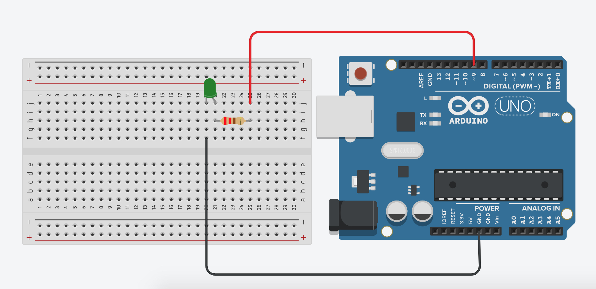
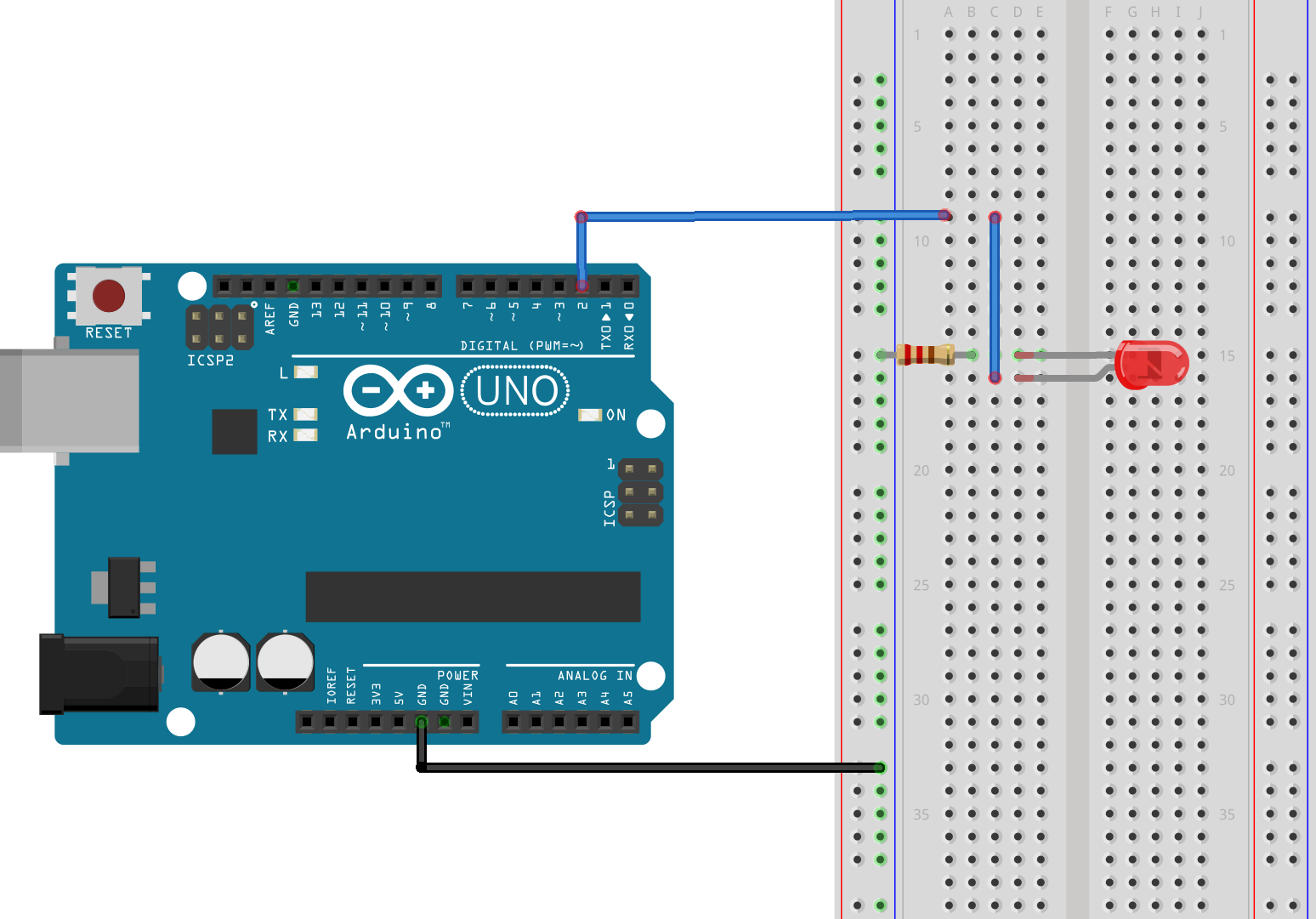
The Arduino software simplifies this process through the analogWrite() function. Despite its name, this function does not write a specific voltage; it sets the duty cycle of the PWM signal. This function accepts a value between 0 and 255. This 8-bit resolution means there are 256 possible discrete levels of power you can provide to your output. For example, calling analogWrite(9, 127) would result in an approximately 50% duty cycle on pin 9.
Resolution and Voltage Calculations for PWM
When designing circuits that require precision, understanding the mathematical relationship between the analogWrite() value and the resulting voltage is essential. On a standard 5V Arduino, the resolution of the PWM output is 8-bit. To find the effective voltage for a given value, you use the following formula: Effective Voltage = (Value / 255) * Reference Voltage.
For instance, if you are using an Arduino Uno (5V) and you set the output value to 100, the calculation would be: (100 / 255) * 5 = 1.96V. While this provides a decent range of control for basic hobbyist applications, it is important to remember that the "steps" between values are roughly 19.6 millivolts. In many 2026 sensor simulation or precision instrument projects, these steps may be too large, leading to jittery behavior in the connected device.
Furthermore, the reference voltage itself is a variable. If your Arduino is powered via a USB port that is only providing 4.8V due to cable resistance, your PWM calculations will be slightly off. For projects where accuracy is paramount, measuring the actual voltage on the 5V or 3.3V pin with a multimeter and substituting that real-world value into your calculations is a best practice. This ensures that your "analogue" simulation remains as close to your target as possible.
Board-Specific PWM Capabilities and Pin Assignments
Not every pin on an Arduino can perform PWM. On the classic Arduino Uno R3, only pins 3, 5, 6, 9, 10, and 11 are PWM-capable. These are usually marked with a tilde (~) on the PCB silkscreen. The frequency of the PWM signal also varies by pin. Pins 5 and 6 typically operate at approximately 980 Hz, while the others operate at 490 Hz. This frequency difference is due to how the ATmega328P microcontroller maps its internal timers to physical pins.
The Arduino Mega 2560 provides significantly more options, offering PWM on pins 2 through 13 and 44 through 46. This makes the Mega ideal for projects requiring multiple analogue-like outputs, such as complex lighting arrays or multi-axis robotics. On the newer Arduino Uno R4 Minima and WiFi models, the PWM capabilities are even more robust, often allowing for higher-resolution PWM (up to 12-bit or 14-bit in some configurations) through advanced library usage, though the standard analogWrite() remains 8-bit for backward compatibility.
When moving to 3.3V boards like the Nano 33 IoT or the MKR series, the PWM pins remain plentiful, but the logic level changes. It is vital to ensure that your connected components are compatible with 3.3V signals. Attempting to drive a 5V-only motor controller or high-brightness LED string with 3.3V PWM may result in insufficient power or failure to trigger the component's internal logic.
Enhancing Signals with Low-Pass RC Filtering
One of the biggest drawbacks of PWM is that it is still a digital signal. If you connect a PWM pin to an oscilloscope, you will see sharp square waves, not a flat line. For applications like audio generation or creating a reference voltage for an analogue circuit, this "noise" is unacceptable. The solution is a Low-Pass RC Filter, a simple circuit consisting of a resistor (R) and a capacitor (C).
The RC filter works by "smoothing" the square waves. The resistor limits the current, and the capacitor stores charge. When the PWM signal is HIGH, the capacitor charges; when it is LOW, the capacitor slowly discharges through the circuit. If the resistor and capacitor values are chosen correctly, the capacitor never fully charges or discharges, resulting in a relatively smooth DC voltage with only a small amount of "ripple" noise.
To design a basic filter for a 490 Hz PWM signal, a common starting point is a 10k Ohm resistor and a 10uF capacitor. The cutoff frequency of the filter can be calculated using the formula: f = 1 / (2 * pi * R * C). You want the cutoff frequency to be significantly lower than the PWM frequency to ensure effective smoothing. However, be aware that a very strong filter will also slow down how quickly your analogue output can change, which may be a disadvantage for high-speed applications.
True Analogue Output: The Rise of the On-Board DAC
As we navigate the technology landscape of 2026, the demand for true analogue output has led to the integration of Digital-to-Analog Converters (DACs) directly onto Arduino boards. Unlike PWM, a DAC produces a real, steady voltage. This is achieved by an internal network of resistors or capacitors that convert a digital number into a corresponding analogue level.
The Arduino Uno R4 Minima is a landmark board in this regard, featuring a built-in 12-bit DAC on pin A0. A 12-bit DAC provides 4,096 discrete voltage levels (0 to 4095). On a 5V scale, this results in a precision of approximately 1.2 millivolts per step, which is vastly superior to the 19.6 millivolts of standard 8-bit PWM. To use this feature, you simply call analogWrite(A0, value). The board automatically recognizes that A0 is a DAC pin and outputs a steady voltage rather than a pulsing signal.
Other boards with true DAC capabilities include the Arduino Zero, the Due (which has two DAC channels), and the Portenta H7. These are the preferred choices for generating high-fidelity audio, precise control signals for scientific instruments, or interfacing with legacy analogue equipment that cannot interpret high-frequency PWM pulses. When using a DAC, it is important to check the datasheet for the specific board, as some DACs can only output up to a certain voltage (e.g., 3.3V) even if the board is powered by 5V.
Advanced Analogue Output via External Modules
If you are using a standard board like an Uno R3 but require the precision of a true DAC, external modules are the most reliable solution. The most popular chip for this purpose is the MCP4725. This is a 12-bit DAC that communicates with the Arduino over the I2C protocol. By using just two wires (SDA and SCL), you can add high-precision analogue output to any microcontroller.
External DACs offer several advantages over built-in PWM:
- On-board EEPROM: Some DACs like the MCP4725 can store a specific voltage level in non-volatile memory, so they output that voltage as soon as they receive power, even before the Arduino finishes booting.
- Isolation: Using an external module can help isolate noisy digital signals from sensitive analogue circuitry.
- Higher Resolution: While Arduino's built-in DACs are typically 10-bit or 12-bit, external I2C or SPI modules can reach 16-bit or even 24-bit resolution for specialized scientific applications.
To implement an external DAC, you typically use a library such as the Adafruit_MCP4725 library. The workflow involves initializing the I2C bus and then sending a command like dac.setVoltage(2048, false) to set the output to 50% of the reference voltage. This approach is highly recommended for projects involving high-end audio synthesis or precision laboratory power supplies.
Practical Applications: From Motors to Audio
The choice between PWM and true analogue depends entirely on the application. For LED dimming, PWM is almost always superior. LEDs respond linearly to the average current provided by PWM, and because they switch on and off faster than the human eye can perceive, the result is perfectly smooth dimming without the color shifting that can occur when lowering the actual voltage.
In motor control, PWM is the industry standard. Most motor drivers (like the L298N or the TB6612FNG) are designed to accept a PWM signal to control speed. The inductance of the motor windings naturally acts as a filter, smoothing out the pulses into mechanical motion. However, if the PWM frequency is too low, the motor may produce an audible high-pitched "whine." In these cases, advanced users often modify the Arduino's internal timer registers to increase the PWM frequency beyond the range of human hearing (above 20 kHz).
For audio projects, true analogue is non-negotiable. While you can produce simple "beeps" and "boops" using the tone() function (which uses a 50% duty cycle square wave), high-quality sound requires a DAC. A DAC allows you to reconstruct complex waveforms like sine waves or recorded speech. If a DAC is not available, a filtered PWM signal can work for low-fidelity audio, but it often lacks the dynamic range and clarity required for modern 2026 multimedia projects.
Safety, Limitations, and Troubleshooting
When working with analogue output, the most common mistake is exceeding the current limits of the Arduino pins. Most standard Arduino pins can only source or sink about 20mA to 40mA of current safely. If you attempt to drive a motor or a high-power LED directly from an analogue pin, you risk permanently damaging the microcontroller's internal circuitry. Always use a transistor, MOSFET, or dedicated driver chip for high-current loads.
Another frequent issue involves "ghosting" or unexpected behavior when using multiple libraries. Many libraries, such as the Servo library, take control of specific internal timers. If the Servo library is using Timer 1, PWM functionality on pins 9 and 10 (which also rely on Timer 1) may be disabled or act erratically. If your analogWrite() commands aren't working, check for library conflicts in your code.
Finally, verify your output with a multimeter or an oscilloscope. If you are using PWM, a standard multimeter set to DC voltage will show the "average" voltage, which is helpful for quick checks. However, if the reading is jumping around, it may be because the meter is trying to sample the rapid pulses of the PWM signal. In such cases, adding a temporary 10uF capacitor across the output can help stabilize the reading for testing purposes.
| Feature | PWM (Pulse Width Modulation) | True DAC (Digital-to-Analog) |
|---|---|---|
| Signal Type | High-frequency square wave (Digital) | Continuous steady voltage (Analogue) |
| Standard Resolution | 8-bit (0-255) | 10-bit to 12-bit (0-1023 or 0-4095) |
| Best For | LEDs, Motors, Servos | Audio, Signal Generation, Lab Equipment |
| Complexity | Built-in, very easy to use | Requires specific pins or external chips |
| Filtering | Often requires an RC filter for DC | No filtering required for DC |
| Accuracy | Dependent on frequency and load | High precision, low noise |
Frequently Asked Questions
Why does my multimeter show 5V when I use analogWrite(9, 128)?
This usually happens if your multimeter is set to a mode that captures peak voltage rather than average voltage, or if the PWM frequency is too low for your meter's sampling rate. To see the "analogue" effect on a meter, you can place a low-pass RC filter (e.g., 10k resistor and 10uF capacitor) between the pin and the meter to smooth the pulses into a steady 2.5V reading.
Can I use any pin for analogue output?
No. On most boards, only specific pins marked with a tilde (~) or specifically designated as DAC pins (like A0 on the Uno R4) support analogWrite(). If you use analogWrite() on a non-PWM pin, the Arduino will typically treat any value below 128 as LOW and any value 128 or above as HIGH, resulting in a simple on/off behavior.
How do I get a 0V to 10V analogue output from an Arduino?
Arduino pins are limited to their operating voltage (5V or 3.3V). To achieve a 0-10V range, you must use an external operational amplifier (Op-Amp) configured in a non-inverting gain setup. For example, a gain of 2 will turn a 0-5V Arduino signal into a 0-10V signal. You will also need an external 12V power supply to power the Op-Amp.
Is PWM the same as "Analog Write" in the code?
Yes, in the Arduino IDE, the command analogWrite() is the software instruction used to trigger the hardware PWM generators. Despite the name, it is a digital process on 90% of Arduino boards. Only on boards with a physical DAC does this command result in a true analogue voltage change.
Can I change the PWM frequency on my Arduino?
Yes, but it requires manipulating the microcontroller's hardware timers directly by changing bits in the TCCR (Timer/Counter Control Register). This is an advanced technique that can interfere with other functions like millis(), delay(), or the Servo library, so it should be handled with care.
Recommended Next Steps
To effectively implement analogue output in your next project, start by identifying whether your application requires a high-frequency pulse (like a motor) or a smooth voltage (like audio). For those using the standard Arduino Uno R3, practicing the construction of a Low-Pass RC filter is the best way to visualize how digital pulses become analogue signals. If your project demands high precision, consider upgrading to an Arduino Uno R4 Minima to take advantage of its built-in 12-bit DAC, or purchase an MCP4725 I2C DAC module for a reliable, external solution that works with any board. Always remember to use a transistor or motor driver if you are controlling anything that draws more than 20mA to protect your hardware.