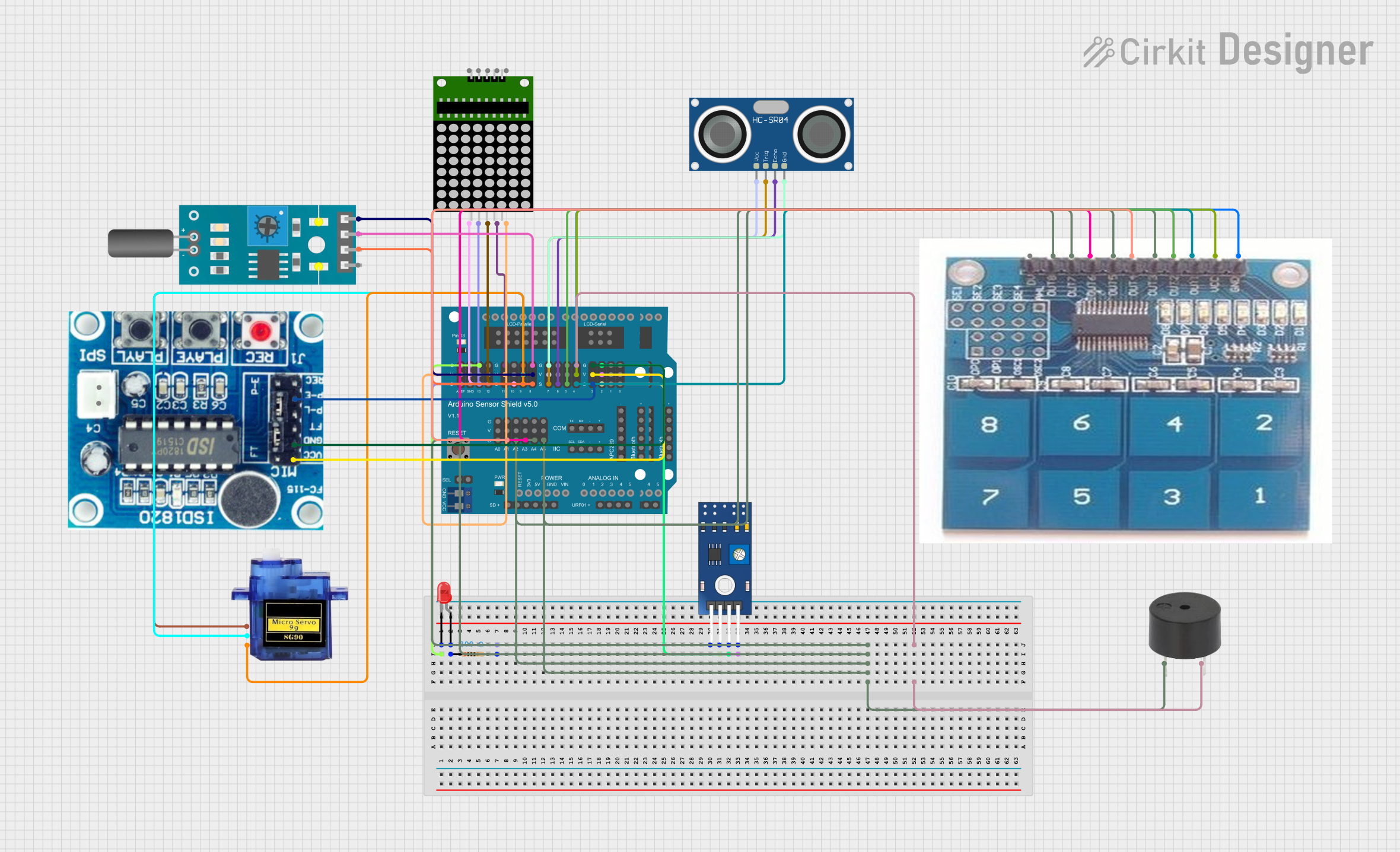
To measure distance with an Arduino using an IR sensor, you must choose between digital proximity sensors for simple obstacle detection or analog triangulation sensors, such as the Sharp GP2Y0A series, for precise centimeter-based readings. These sensors emit infrared light and interpret the reflection to calculate the distance between the sensor and a target object.
Infrared (IR) distance sensing remains one of the most fundamental skills for any electronics enthusiast, robotics engineer, or IoT developer. As of 2026, despite the proliferation of sophisticated LiDAR and ultrasonic alternatives, IR sensors continue to be favored for their low cost, small form factor, and high-speed response times in indoor environments. Whether you are building a self-navigating robot, a touchless soap dispenser, or an industrial proximity counter, understanding the technical nuances of how Arduino interacts with these sensors is critical for project success.
Understanding the Categories of IR Distance Sensors
When searching for an "Arduino IR sensor distance" solution, it is vital to distinguish between the three primary types of hardware available. Each operates on a different physical principle and provides a different type of data to the Arduino microcontroller.
1. Digital Proximity Sensors (Obstacle Avoidance)
The most common and least expensive modules are basic IR obstacle avoidance sensors. These typically feature an IR emitting LED and a photodiode receiver. They do not provide a specific distance in centimeters. Instead, they feature an onboard potentiometer that allows you to set a threshold. When an object comes within the "trigger zone," the output pin flips from HIGH to LOW (or vice-versa). These are best suited for simple "yes/no" detection tasks where exact measurement is irrelevant.
2. Analog Triangulation Sensors
The Sharp GP2Y0A series represents the gold standard for analog IR distance measurement. Unlike basic modules that rely on the intensity of reflected light, these sensors use a lens and a linear charge-coupled device (CCD) array to perform triangulation. The angle of the reflected light changes based on the distance of the object, which the sensor converts into a variable voltage. Because they use angle rather than intensity, they are significantly less affected by the color or reflectivity of the object being measured.
3. Time-of-Flight (ToF) IR Sensors
Technically using an infrared laser (VCSEL), Time-of-Flight sensors like the VL53L0X measure the time it takes for photons to travel to an object and back. While more complex to program, they offer millimeter precision and are much more resilient to ambient light interference. These sensors communicate with the Arduino via the I2C protocol rather than a simple analog pin.
The Physics of IR Distance Measurement
To effectively implement an IR sensor, you must understand the two main methods by which they interpret distance: Intensity and Triangulation.
Intensity-based sensing relies on the Inverse Square Law. As the distance from the light source increases, the intensity of the light hitting the object decreases, and the intensity of the light reflected back to the sensor decreases even further. The primary flaw here is that a dark object close to the sensor might reflect the same amount of light as a bright object far away, leading to "false" distance readings.
Triangulation, used by higher-quality analog sensors, is far more robust. The emitter sends out a beam of IR light. This beam hits a surface and reflects in multiple directions. A small lens on the receiver side focuses the reflected light onto a specific point on an internal sensing strip. As the object moves closer or further away, the angle of the reflection changes, shifting the point of impact on the sensing strip. The sensor then outputs a voltage (typically between 0.4V and 3V) that corresponds to that specific angle.
Hardware Requirements and Wiring
Setting up an IR distance sensor with an Arduino (such as the Uno R3, R4, or Nano) is straightforward. For a standard analog sensor like the Sharp GP2Y0A21YK0F (10cm to 80cm range), you will need:
- Arduino Microcontroller: Any 5V or 3.3V board (ensure sensor compatibility).
- IR Distance Sensor: Analog or Digital module.
- Jumper Wires: Typically three (VCC, GND, and Signal).
- Capacitor (Optional but Recommended): A 10uF capacitor across the VCC and GND pins near the sensor helps stabilize the voltage, as IR sensors can draw sharp bursts of current that cause noise in the readings.
Wiring Diagram Logic:
- VCC: Connect to the 5V pin on the Arduino.
- GND: Connect to the Ground pin on the Arduino.
- Signal (Out): Connect to an Analog Input pin (e.g., A0) for analog sensors, or a Digital Input pin (e.g., D2) for proximity modules.
Programming the Arduino for IR Distance
Interpreting the data from an IR sensor requires more than a simple reading of a pin. Because the relationship between the voltage output and the actual distance is non-linear (it follows a 1/x curve), you must apply a mathematical formula or a look-up table in your code.
Reading Digital Sensors
For digital obstacle modules, the programming is elementary. You define the pin as an INPUT, and in the main loop, you use the digitalRead function. If the value is LOW, an object is detected. This is ideal for high-speed applications like line following or revolution counting where you do not need to know the specific distance.
Reading Analog Sensors
For analog sensors, you use the analogRead function, which returns a value between 0 and 1023 (on a 10-bit ADC). To convert this into centimeters, you generally use a formula derived from the sensor's datasheet. A common formula for the 10-80cm Sharp sensor is: Distance (cm) = 29.988 * pow(Analog_Value, -1.173).
Alternatively, many developers use the multiMap library or create a custom look-up table to interpolate distances based on the voltage. This is often more accurate because it allows you to account for the "dead zone" (distances closer than 10cm where the voltage actually starts to drop again, causing ambiguous readings).
Technical Specifications and Comparison
Choosing the right sensor depends on your specific range requirements and the environment in which the sensor will operate.
| Sensor Model | Detection Method | Range | Output Type | Best Use Case |
|---|---|---|---|---|
| TCRT5000 | Intensity | 1mm - 25mm | Digital/Analog | Line following, short proximity |
| Sharp GP2Y0A21 | Triangulation | 10cm - 80cm | Analog | General robotics, obstacle avoidance |
| Sharp GP2Y0A710 | Triangulation | 100cm - 550cm | Analog | Long-range indoor mapping |
| VL53L0X (ToF) | Time-of-Flight | 2cm - 200cm | I2C (Digital) | High precision, varying object colors |
| Generic IR Module | Intensity | 2cm - 30cm | Digital | Simple DIY security, touchless switches |
Calibration and Data Smoothing Strategies
One of the most significant challenges with Arduino IR sensors is signal noise. Because infrared light is all around us (emitted by the sun, light bulbs, and even human bodies), the raw analog data can be "jittery."
To combat this, implementation should include a Moving Average Filter. Instead of taking a single reading and acting on it, the Arduino should take 10 to 20 readings in quick succession, store them in an array, and calculate the average. This flattens out the spikes caused by external IR interference and provides a much smoother distance value for your project.
Another critical calibration step is handling the Minimum Distance Limitation. Most triangulation sensors have a "blind spot." If an object is 2cm away from a sensor rated for a 10cm minimum, the sensor will often output a voltage that suggests the object is much further away. In a robotics context, this can lead to collisions. Experienced builders often mount their sensors recessed into the robot chassis to ensure that any potential obstacle is always at least 10cm away from the sensor face.
Environmental Considerations and Limitations
While IR sensors are versatile, they are not universal solutions. Users must account for several physical limitations during the design phase:
- Ambient Light Interference: Direct sunlight is saturated with infrared radiation. Most IR sensors will fail or provide highly inaccurate data when used outdoors during the day. For outdoor use, ultrasonic (sonar) or shielded LiDAR sensors are preferred.
- Surface Reflectivity (Albedo): Although triangulation sensors are better at handling different colors, extremely dark surfaces (like black matte paint) absorb IR light rather than reflecting it. This can cause the sensor to "miss" an object entirely. Conversely, mirrors or highly polished metal can reflect the beam away from the receiver, resulting in no reading.
- Field of View (FoV): IR sensors have a very narrow beam compared to ultrasonic sensors. While this is great for pinpointing an object, it means the sensor might miss a thin chair leg or a small obstacle that is slightly off-axis.
Advanced Applications in 2026
By 2026, the integration of IR distance sensing with Arduino has moved beyond simple obstacle avoidance.
- Gesture Control: By using an array of three or four IR sensors, developers are creating touchless interfaces where hand movements (swiping, pushing, or circling) are interpreted as commands for smart home devices.
- Slam and Mapping: While LiDAR is the king of mapping, low-cost IR sensor arrays are being used in "Micro-SLAM" projects where small, inexpensive robots map indoor rooms by rotating a Sharp sensor on a servo motor.
- Industrial Safety Curtains: Using multiple digital IR pairs to create an invisible grid that shuts down machinery if a human hand breaks the plane, providing a low-cost safety alternative for small-scale workshops.
Common Mistakes to Avoid
- Ignoring the Voltage Drop: IR sensors draw more current when the IR LED pulses. If your Arduino is powered via a weak USB port and is also driving servos, the sensor readings will fluctuate wildly. Always use a stable, external power supply for projects involving multiple components.
- Incorrect Pin Mode: Forgetting to set the pin mode to INPUT or using a digital pin for an analog sensor (and vice-versa) is a frequent source of frustration for beginners.
- Poor Mounting: Mounting the sensor behind a thick piece of clear acrylic can interfere with the IR beam. If you must protect the sensor, use a specialized IR-transparent window or ensure the lenses are flush with the cutout.
Frequently Asked Questions
Can IR sensors measure distance through glass?
IR sensors generally struggle with glass. While the IR light can pass through, a significant portion of it reflects off the surface of the glass back into the receiver, causing the sensor to think an object is much closer than it actually is. Furthermore, many types of modern glass have IR-blocking coatings.
Why is my IR sensor giving different readings for black and white objects?
If you are using a low-cost intensity-based sensor, it cannot distinguish between distance and reflectivity. A white object reflects more light than a black one, so the sensor interprets the white object as being closer. To fix this, switch to a triangulation sensor like the Sharp GP2Y0A series or a Time-of-Flight sensor.
What is the maximum distance an Arduino IR sensor can measure?
For standard consumer-grade analog IR sensors, the maximum reliable range is typically around 5.5 meters (using models like the Sharp GP2Y0A710). For longer distances, you would need to transition to laser-based LiDAR systems which can reach 40 meters or more.
How do I connect an IR sensor to a 3.3V Arduino like the Nano Every or ESP32?
Most classic Sharp IR sensors require 5V for power. If you are using a 3.3V logic microcontroller, you can still power the sensor with 5V, but you must use a voltage divider (resistors) on the signal output pin to ensure the voltage entering the Arduino does not exceed 3.3V, which could damage the board.
Are IR sensors better than ultrasonic sensors?
It depends on the application. IR sensors are faster, have a narrower beam (good for narrow spaces), and are not affected by soft materials like foam or cloth. Ultrasonic sensors are better in bright sunlight, have a wider detection area, and are unaffected by the color or transparency of the object.
Practical Recommendation
For most intermediate Arduino projects, the Sharp GP2Y0A21YK0F (10-80cm) is the best balance of cost, ease of use, and accuracy. It avoids the pitfalls of cheap digital modules while remaining significantly simpler to code than I2C-based ToF sensors. When implementing this sensor, always include a 10uF capacitor and a moving average filter in your software to ensure the most stable and professional results for your hardware application.