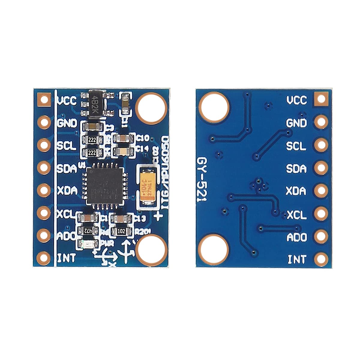
The MPU-6050 sensor remains a cornerstone of low-cost motion tracking, combining a 3-axis accelerometer and a 3-axis gyroscope into a single microelectromechanical system (MEMS) package with an integrated Digital Motion Processor. Despite the introduction of newer inertial measurement units, it continues to dominate hobbyist electronics, educational robotics, and rapid prototyping due to its accessible I2C interface and extensive software library support.
Evolution and Core Architecture of the MPU-6050
Understanding the MPU-6050 requires examining how it bridged a major technological gap upon its release by InvenSense (now part of TDK Corporation). Before its introduction, integrating multi-axis accelerometers and gyroscopes meant dealing with discrete components, complex calibration routines, and separate communication lines. The MPU-6050 revolutionized the embedded systems landscape by integrating a 3-axis accelerometer and a 3-axis gyroscope onto a single silicon die, complemented by a hardware-accelerated engine designed to process complex motion algorithms.
At the heart of the architecture is the Digital Motion Processor (DMP). The DMP is designed to offload computation from the host microcontroller, such as an Arduino or STM32. Instead of forcing the main processor to constantly poll raw data and execute resource-heavy sensor fusion algorithms—like complementary filters or Kalman filters—the DMP can compute Quaternion outputs directly on the chip. This design choice preserves precious processing cycles on the host microcontroller, making the sensor ideal for resource-constrained environments.
The sensor communicates primarily via an Inter-Integrated Circuit (I2C) interface, operating as a slave device up to 400 kHz. Additionally, it features an auxiliary I2C master bus, known as the I2C Master interface, which allows the MPU-6050 to directly read external sensors, such as a 3-axis magnetometer. When connected to an external compass, the assembly transforms into a full 9-axis Inertial Measurement Unit (IMU), providing absolute heading data alongside linear acceleration and rotational velocity.
Technical Specifications and Performance Metrics
Evaluating the performance of the MPU-6050 requires looking at its configurable measurement ranges and electrical characteristics. Both the accelerometer and the gyroscope feature programmable full-scale ranges, allowing engineers to tailor the sensor sensitivity to the specific application environment.
| Parameter | Accelerometer Specification | Gyroscope Specification |
|---|---|---|
| Full-Scale Range (FSR) | ±2g, ±4g, ±8g, ±16g | ±250, ±500, ±1000, ±2000 °/s |
| ADC Resolution | 16-bit ADCs for each axis | 16-bit ADCs for each axis |
| Operating Current | ~3.6 mA (combined active mode) | ~3.6 mA (combined active mode) |
| Sleep Mode Current | ~5 µA | ~5 µA |
| Digital Output | I2C up to 400 kHz | I2C up to 400 kHz |
The 16-bit analog-to-digital converters (ADCs) provide high resolution across all six axes. For instance, at the most sensitive ±2g accelerometer setting, the output scale factor is typically 16,384 LSB/g, enabling the detection of subtle tilts and vibrations. Similarly, the gyroscope offers a sensitivity scale factor of 131 LSB/(°/s) at the ±250 °/s setting.
Power management is another strong point of the architecture. The device operates on a digital supply voltage (VDD) of 2.375V to 3.46V, while the digital interface logic operates on a separate VLOGIC supply down to 1.71V. This dual-supply design ensures seamless level-shifting when interfacing with modern 3.3V microcontrollers as well as legacy 5V systems through appropriate pull-up resistors and logic level converters. Furthermore, the low-power sleep mode drawing approximately 5 microamperes makes the sensor viable for battery-powered wearable devices and remote wireless sensor nodes.
Common Applications Across Industry Segments
The versatility of the MPU-6050 has secured its place across a wide variety of engineering disciplines and hobbyist projects. Its primary domain remains educational robotics and amateur drone development, where stabilization is critical.
- Self-Balancing Robots: Two-wheeled robots rely on the pitch data calculated from the accelerometer and gyroscope to dynamically adjust motor speeds, maintaining an upright posture against external disturbances.
- Quadcopters and Flight Controllers: Early and custom multirotor flight control boards utilized the MPU-6050 combined with PID control loops to stabilize roll, pitch, and yaw rates in real-time.
- Human-Computer Interaction (HCI): Wearable gesture controllers use the orientation data to translate hand movements into digital commands, enabling wireless presentation clickers, virtual reality tracking, and assistive technology devices.
- Structural Health Monitoring: Civil engineers deploy low-cost sensor arrays featuring the MPU-6050 to measure vibrations, resonant frequencies, and seismic responses in scale models and bridges.
Practical Integration Challenges and Mitigation Strategies
While the MPU-6050 is user-friendly, real-world deployment presents distinct technical challenges that developers must navigate to ensure reliable operation. Signal noise, bias drift, and thermal sensitivity are inherent characteristics of low-cost MEMS sensors that require deliberate software and hardware countermeasures.
Managing Gyroscope Bias Drift
Over time, integrating gyroscope angular velocity data to calculate relative angle results in cumulative error, commonly known as drift. Even a minute offset in the zero-rate output level compounds rapidly, rendering long-term absolute positioning unreliable. To mitigate this, developers implement sensor fusion algorithms. By combining the responsive short-term data of the gyroscope with the long-term gravitational reference of the accelerometer, a complementary filter or a discrete Kalman filter continuously corrects the drift.
Addressing Mechanical Vibrations and Noise
Motors, spinning propellers, and surface irregularities introduce high-frequency mechanical noise that can saturate the MPU-6050 internal buffers and skew sensor readings. The device includes a built-in Digital Low-Pass Filter (DLPF) with configurable bandwidth settings ranging from 5 Hz to 256 Hz. Configuring the internal DLPF correctly suppresses high-frequency noise before it reaches the application layer. Additionally, mounting the sensor breakout board on vibration-damping materials, such as silicone gel pads or soft foam, physically isolates the MEMS structure from external mechanical disturbances.
I2C Bus Management and Addressing
The MPU-6050 communicates over the I2C protocol, which uses dedicated Serial Data (SDA) and Serial Clock (SCL) lines. The sensor address is determined by the state of the AD0 pin. When AD0 is connected to ground (LOW), the 7-bit I2C address is 0x68. When connected to VCC (HIGH), the address shifts to 0x69. This feature allows developers to connect two MPU-6050 sensors to a single microcontroller I2C bus without address conflicts. However, because I2C is sensitive to capacitance and pull-up resistor values, bus lengths should be kept short, and proper 4.7kΩ pull-up resistors must be utilized to maintain signal integrity.
Comparative Overview in the Modern Sensor Landscape
As sensor technology has advanced, newer alternatives have emerged that offer improved noise performance, lower power consumption, or integrated processing units. Understanding how the MPU-6050 compares to contemporary components clarifies its current positioning in hardware design.
- MPU-6050 vs. MPU-9250: The MPU-9250 adds a 3-axis magnetometer (AK8963) to the silicon package, providing native 9-axis motion tracking without requiring an external compass IC on the auxiliary I2C bus.
- MPU-6050 vs. ICM-20948 / ICM-42688-P: Newer TDK InvenSense devices offer significantly lower noise density, wider operating temperature ranges, improved temperature stability, and advanced FIFO management features designed for high-performance industrial and consumer electronics.
Despite these advanced successors, the MPU-6050 maintains unmatched documentation, community support, and cost-effectiveness. For prototyping, prototyping-to-production learning curves, and projects where ultra-high precision is secondary to budget and ease of use, the sensor remains a viable choice.
Frequently Asked Questions
What is the primary function of the MPU-6050?
The MPU-6050 is a 6-axis MotionTracking device that combines a 3-axis accelerometer and a 3-axis gyroscope on a single silicon die. Its primary function is to measure linear acceleration, gravitational forces, and rotational velocity, allowing embedded systems to track motion, orientation, and tilt angles in real-time.
How do I resolve I2C communication errors with the MPU-6050?
Communication errors typically stem from incorrect wiring, missing pull-up resistors on the SDA and SCL lines, or incorrect power supply voltage. Ensure your VCC is connected to 3.3V (or 5V if the breakout board includes an onboard voltage regulator) and verify that the AD0 pin is tied correctly to ground or VCC to match your code's designated I2C address.
Can the MPU-6050 measure absolute heading or direction?
By itself, the MPU-6050 measures acceleration and rotation rates, but it cannot measure absolute magnetic heading (yaw) relative to the Earth's magnetic poles, as it lacks a magnetometer. To obtain absolute heading, you must connect an external magnetometer—such as the HMC5883L or QMC5883L—to the auxiliary I2C master pins of the MPU-6050.
Why does my MPU-6050 gyroscope output drift over time?
Gyroscope drift is an inherent physical characteristic caused by bias instability and thermal fluctuations in MEMS elements. When you integrate angular velocity to calculate position, small constant errors accumulate continuously. This is mitigated by implementing a sensor fusion algorithm that uses the accelerometer to correct long-term drift.
What is the purpose of the onboard Digital Motion Processor (DMP)?
The DMP is an integrated hardware engine inside the MPU-6050 designed to process complex sensor fusion algorithms internally. By calculating quaternions and orientation matrices on the chip, the DMP offloads heavy mathematical computations from the host microcontroller, freeing up processing power for other system tasks.
Conclusion and Next Actions
The MPU-6050 remains an accessible entry point into inertial navigation and motion processing. To begin working with the sensor, secure a tested breakout board, verify your power supply connections, and establish basic communication via a standard I2C scanner script. From there, implement software filtering or leverage the DMP engine to stabilize your specific robotic, wearable, or measurement project.