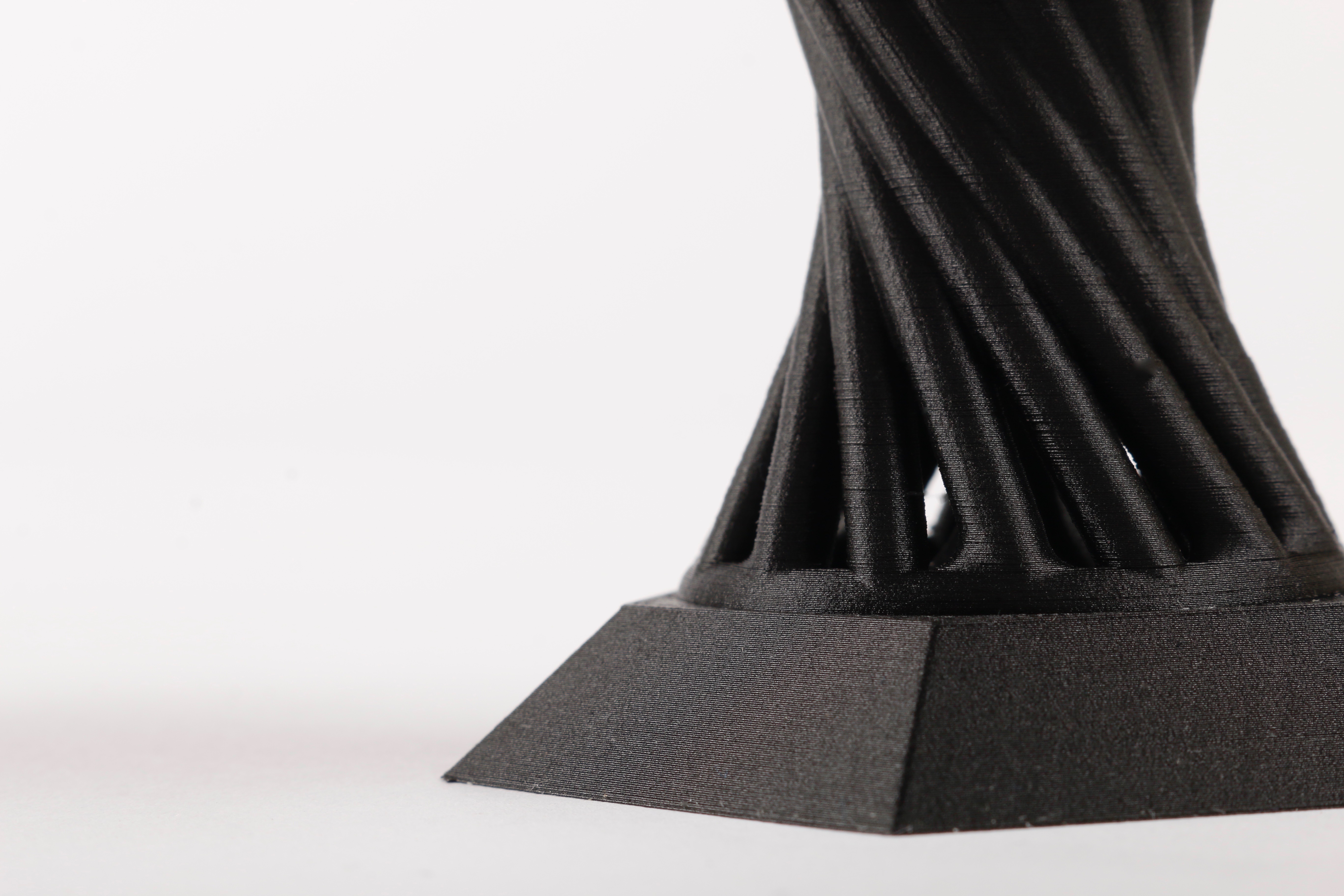
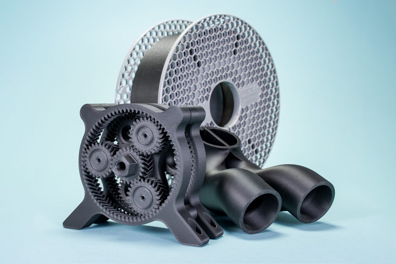
3D printing carbon fiber parts involves reinforcing standard thermoplastics with short or continuous carbon fibers using specialized fused filament fabrication or continuous fiber fabrication printers, resulting in exceptional strength-to-weight ratios and rigidity suitable for functional end-use applications.
Engineering components that require high structural integrity while minimizing weight often lead designers and manufacturers toward advanced composite materials. Traditional manufacturing methods for carbon fiber, such as hand layup, autoclave curing, and compression molding, demand expensive tooling, extensive labor, and complex machining processes. Additive manufacturing offers a compelling alternative by enabling the direct production of complex geometries without dedicated molds.
However, successfully 3D printing carbon fiber parts requires an understanding of material science, printer hardware limitations, post-processing requirements, and mechanical design principles. This guide examines the core methods, material categories, equipment considerations, operational challenges, and practical implementation strategies needed to produce functional carbon fiber composite components.
Understanding Carbon Fiber Reinforcement in 3D Printing
Carbon fiber in additive manufacturing is not a standalone structural material; rather, it functions as a high-performance reinforcing agent embedded within a polymer matrix. The fundamental mechanics of these composites rely on the transfer of stress from the softer, more flexible polymer matrix to the exceptionally stiff and strong carbon fibers.
When evaluating these materials, it is vital to distinguish between two primary categories of carbon fiber reinforcement used in desktop and industrial additive manufacturing: chopped (or short) carbon fibers and continuous carbon fibers.
Short vs. Continuous Carbon Fiber Filaments
Short carbon fiber filaments consist of standard thermoplastic base polymers—such as PLA, PETG, ABS, Nylon, or PEEK—infused with finely chopped carbon fibers, typically ranging from 0.1 mm to 0.5 mm in length. These filaments are fed through standard or modified desktop and industrial printers. The primary benefits of short carbon fibers are increased stiffness, reduced thermal expansion, and improved surface finish. However, because the fibers are short and randomly oriented during extrusion, the gains in tensile and impact strength are more modest compared to continuous alternatives.
Continuous carbon fiber printing, pioneered commercially by manufacturers like Markforged, utilizes a dual-nozzle system. One nozzle extrudes a neat thermoplastic matrix, while the second nozzle lays down a continuous strand of continuous carbon fiber along high-stress load paths. This technique yields mechanical properties that rival or exceed traditional aerospace-grade aluminum, offering remarkable directional strength and impact resistance.
| Feature / Property | Short Carbon Fiber (Chopped) | Continuous Carbon Fiber |
|---|---|---|
| Hardware Requirement | Standard FDM with hardened nozzle | Specialized dual-nozzle or fiber-infusion printer |
| Fiber Length | 0.1 mm – 0.5 mm | Continuous strands (spooled) |
| Primary Benefit | Dimensional stability, stiffness, ease of printing | Extreme tensile strength, structural load-bearing capacity |
| Anisotropy | Low to moderate | High (strength is directional along fiber paths) |
| Material Cost | Moderate ($40 – $150 per kg) | High (proprietary spools and systems) |
Selecting the Right Base Polymer Matrix
The performance of a 3D-printed carbon fiber part is heavily dictated by the polymer matrix holding the fibers together. Selecting the appropriate base material requires balancing environmental conditions, mechanical demands, and printer capabilities.
Nylon (Polyamide) and High-Temperature Engineering Plastics
Nylon is widely regarded as the premier matrix for carbon fiber composites due to its superior layer adhesion, toughness, and chemical resistance. Carbon fiber-filled nylons exhibit exceptional fatigue resistance and impact absorption. For extreme industrial environments, high-performance thermoplastics like PEEK (Polyetheretherketone) and PEI (Ultem) reinforced with carbon fiber offer continuous use temperatures exceeding 200°C and superior flame retardancy, though they require enclosed printers capable of chamber temperatures above 90°C.
Commodity Polymers with Carbon Infusion
Materials like PLA and PETG are also available with chopped carbon fiber reinforcement. While these composites offer increased stiffness and a matte, aesthetic finish that hides layer lines, they do not match the toughness or heat deflection of engineering-grade matrices. They are generally suited for enclosures, jigs, fixtures, and non-structural prototypes rather than load-bearing mechanical assemblies.
Hardware Requirements and Equipment Modifications
Printing composite filaments containing abrasive carbon fibers introduces significant engineering challenges at the hardware level. Unmodified 3D printers will experience rapid degradation when processing these materials.
Extruder and Nozzle Wear
Carbon fibers are intensely abrasive. Standard brass nozzles will widen and deform within a single spool of carbon fiber filament, ruining print tolerance and extrusion consistency. Upgrading to hardened steel, tool steel, or ruby-tipped nozzles is mandatory. Furthermore, direct-drive extruders are preferred over Bowden tube setups because the rigid, brittle nature of carbon-infused filament makes it prone to snapping inside long, curved feed tubes.
Enclosure and Filtration Systems
Engineering-grade composites, particularly nylons and high-temperature filaments, demand heated build chambers to prevent warping and internal stress buildup. Additionally, printing these materials releases ultrafine particles and volatile organic compounds (VOCs). Enclosures equipped with HEPA and activated carbon filtration are necessary to maintain a safe working environment, especially in office or non-industrial settings.
Design Considerations for Additive Composites
Designing parts for carbon fiber 3D printing requires moving away from isotropic design mentalities and embracing the directional nature of composite materials.
Fiber Orientation and Load Paths
When utilizing continuous fiber printing software, engineers must designate specific layers and vector paths where continuous fibers are deposited. Placing fibers along known tensile or bending axes maximizes structural efficiency. Ignoring load paths can result in delamination or structural failure under multi-axial loads.
Minimizing Stress Concentrations
Sharp internal corners act as stress concentrators that can initiate cracks within a composite matrix. Incorporating generous fillets and radiused transitions ensures smooth load transfer across the part geometry. Additionally, designers should account for anisotropic shrinkage; carbon-filled materials shrink significantly less than neat polymers during cooling, which improves dimensional accuracy but requires careful tolerance planning for mating assemblies.
Post-Processing and Finishing Techniques
Achieving final functional requirements often necessitates post-processing operations.
Annealing and Thermal Conditioning
Nylon-based carbon fiber prints absorb ambient moisture rapidly, which affects their mechanical properties and dimensional stability. Post-print conditioning—often involving controlled thermal annealing in an oven or moisture conditioning in a warm water bath—relieves internal residual stresses and optimizes crystallinity, yielding maximum tensile strength and heat resistance.
Machining and Surface Preparation
Because carbon fiber composites are difficult to smooth via sanding alone due to the hardness of the embedded fibers, mechanical post-processing such as CNC milling, drilling, or tapping is frequently required for precision mounting holes. Technicians must wear appropriate respiratory protection and use dust extraction systems when cutting or sanding carbon fiber to prevent the inhalation of hazardous micro-fibers.
Common Challenges and Troubleshooting
Even with high-end equipment, operators frequently encounter specific failure modes when 3D printing carbon fiber parts.
- Clogging and Jamming: Caused by fiber agglomeration or heat creep in the cold zone of the hotend. Mitigate this by using larger nozzle diameters (minimum 0.4 mm, preferably 0.6 mm) and ensuring adequate hotend cooling.
- Layer Delamination: Occurs when interlayer adhesion is insufficient due to low ambient or bed temperatures. Increase chamber temperatures and dry the filament thoroughly prior to printing.
- Stringing and Oozing: High-temperature polymers combined with carbon fibers can exhibit stringing if retraction settings are not tightly calibrated. Optimize retraction distance and speed while maintaining a dry filament state.
Summary of Implementation Steps
Transitioning successfully to carbon fiber additive manufacturing requires a systematic workflow:
- Define mechanical and thermal requirements to select the appropriate polymer matrix (e.g., Nylon vs. PETG).
- Equip the printer with hardened steel components, direct-drive extrusion, and a filtered enclosure.
- Optimize CAD models specifically for composite load paths and anisotropic behavior.
- Calibrate slicer settings, specifically lowering print speeds and adjusting retraction parameters.
- Implement proper post-processing, including moisture conditioning and precise mechanical fastening preparation.
Frequently Asked Questions
Can I print carbon fiber filament on a standard stock 3D printer?
You can technically feed carbon fiber filament into a stock printer, but the abrasive fibers will rapidly wear out standard brass nozzles and aluminum drive gears. You must upgrade to a hardened steel nozzle and wear-resistant extruder gears before attempting to print abrasive composite filaments.
Are 3D printed carbon fiber parts as strong as traditionally molded carbon fiber?
Generally, no. While continuous carbon fiber 3D printing approaches the strength of traditional hand layup in specific vector directions, traditionally molded and autoclaved carbon fiber parts achieve higher fiber volume fractions and uniform multi-directional strength that additive manufacturing cannot fully replicate.
Does carbon fiber filament need to be dried before printing?
Yes. Most engineering polymers used as matrices for carbon fiber—such as Nylon and PETG—are hygroscopic, meaning they absorb moisture from the air. Printing wet filament leads to steam vaporization in the hotend, resulting in poor surface finish, weak layer adhesion, and internal bubbling.
What nozzle size is best for printing carbon fiber composites?
A 0.4 mm nozzle is the absolute minimum, but a 0.6 mm nozzle is widely recommended. Smaller nozzles are highly susceptible to clogging because aggregated carbon fibers can bridge the nozzle opening and halt extrusion.
How do I prevent printed carbon fiber parts from warping?
Warping is typically caused by rapid thermal contraction. Using a heated build chamber, applying specialized adhesives to the build plate, and ensuring the printer is shielded from external drafts will significantly reduce thermal gradient warping.