The ATX (Advanced Technology eXtended) form factor defines the physical dimensions (12 × 9.6 inches or 305 × 244 mm), mounting hole patterns, backplane I/O placement, and electrical power specifications for standard desktop motherboards. Introduced by Intel in 1995, modern ATX motherboards combine legacy layout guidelines with contemporary power standards—such as ATX 3.1 and ATX12VO—to deliver high-power PCIe 5.0 graphics, DDR5 memory, and advanced thermal management across modern PC architectures.
The Evolution of ATX: From 1995 Roots to Modern Standards
Prior to the introduction of the ATX standard in 1995, personal computers primarily relied on the AT (Advanced Technology) and Baby AT form factors. These legacy layouts suffered from significant design limitations: expansion cards frequently overlapped with the CPU socket, system cooling relied on haphazard airflow paths, and integrated input/output (I/O) ports required long ribbon cables running from the motherboard to external chassis cutouts.
Intel designed the ATX standard to resolve these structural bottlenecks. By rotating the motherboard layout 90 degrees relative to the chassis expansion slots, ATX placed the processor and memory sockets away from the primary expansion area. This architectural change allowed full-length PCI and ISA cards to be installed without physical obstruction. Furthermore, ATX integrated the rear I/O connectors directly onto a dedicated panel on the motherboard, eliminating internal cable clutter and simplifying system assembly.
ATX Board Layout Overview:
- Rear I/O Panel
- CPU Socket Area (High-Phase VRM Heatsinks)
- DDR5 DIMM Slots (Dual/Quad Channel)
- M.2 PCIe 5.0 NVMe Slot with Thermal Shield
- Primary PCIe 5.0 x16 Slot (Reinforced Steel Armored)
- Chipset / PCH Heatsink
- 24-Pin ATX / Front USB-C Header
- PCIe Expansion Slot
- M.2 PCIe 4.0 Slot
- Audio Codec Block
- SATA / Board Headers
Over the past three decades, the ATX specification has continually evolved to accommodate exponential increases in power consumption, bus bandwidth, and thermal dissipation. The original 20-pin main power connector expanded to a 24-pin design (ATX12V 2.0) to supply additional current to PCI Express slots. Subsequent revisions integrated dedicated 4-pin and 8-pin EPS12V connectors to feed energy-dense Central Processing Units (CPUs).
In modern desktop systems, the ATX specification serves as both a physical geometry template and an electrical compliance baseline. While the external dimensions of a standard ATX board remain identical to the 1995 baseline, the internal trace routing, layer count (often 6 to 8 layers of copper PCB), and power delivery topologies have fundamentally transformed to support high-frequency signals like PCIe 5.0 and DDR5 memory modules.
Physical Specifications and Mechanical Dimensions
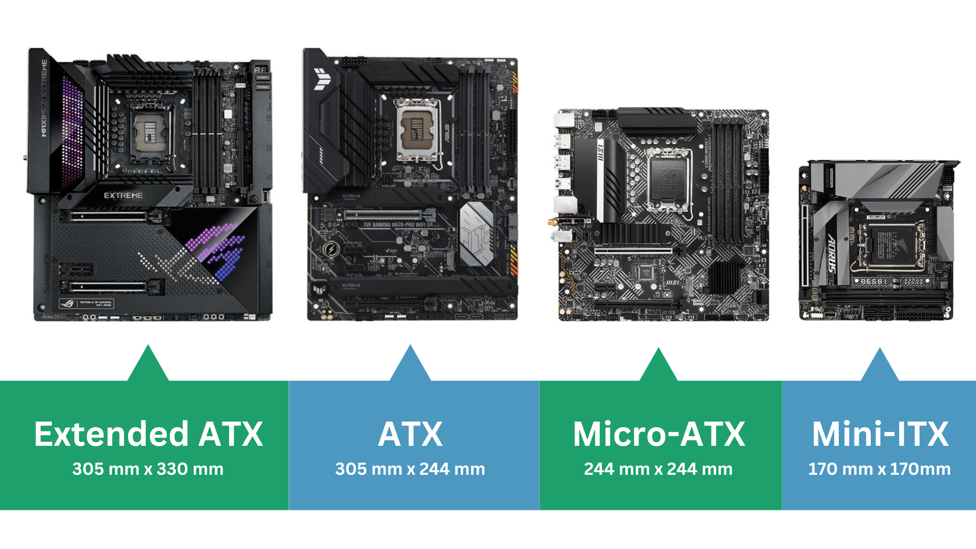
Motherboard form factors dictate case selection, thermal headroom, component clearance, and expansion capacity. While ATX remains the primary standard for enthusiast and workstation systems, derivative form factors cater to compact or oversized build requirements.
Comparison of Motherboard Form Factors
| Form Factor | Dimensions (mm) | Dimensions (inches) | Typical PCIe Expansion Slots | Memory Slots | Primary Use Case |
|---|---|---|---|---|---|
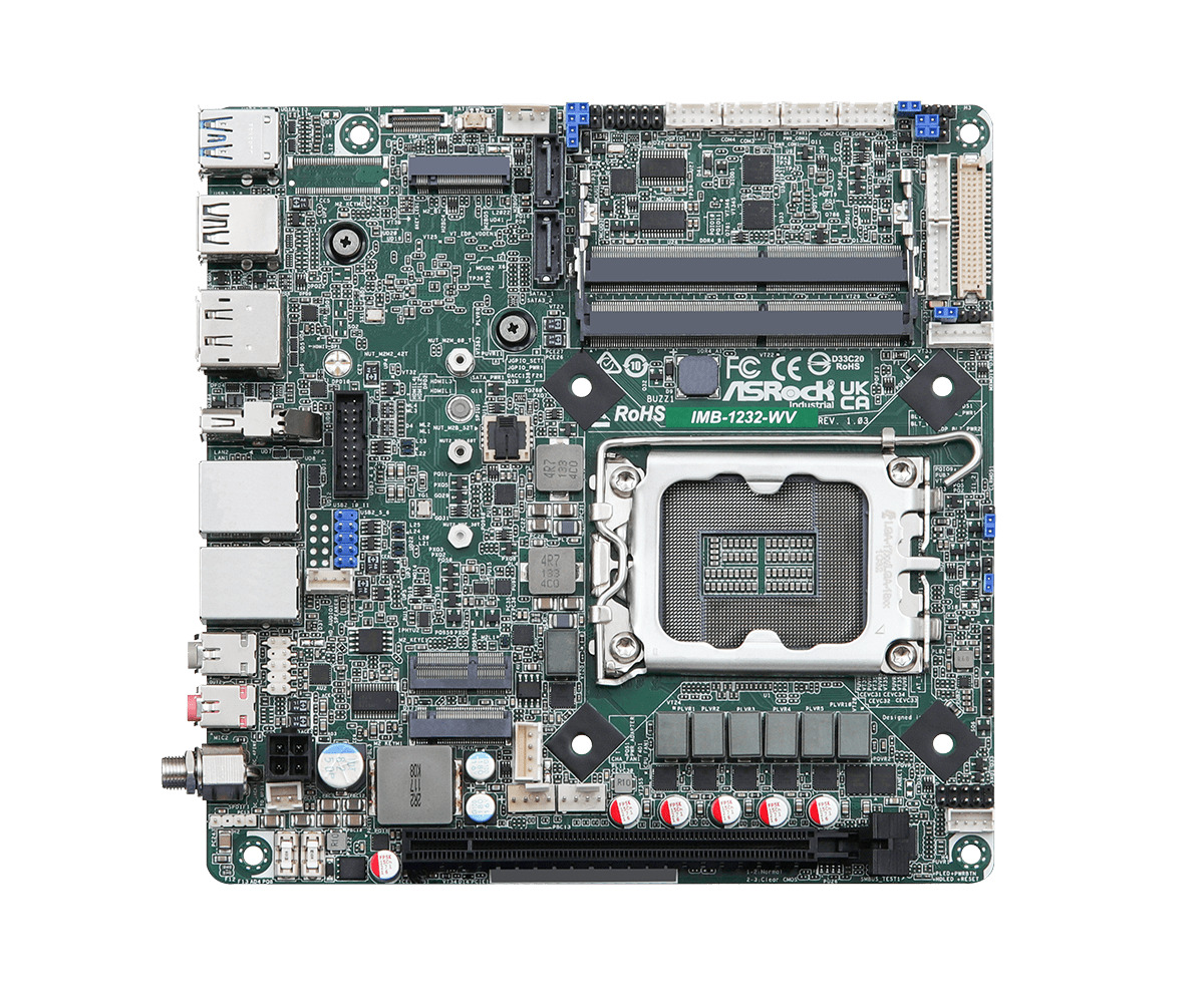
| Mini-ITX | 170 × 170 mm | 6.7 × 6.7 in | 1 x16 slot | 2 DIMM | Small Form Factor (SFF), ultra-compact PCs |
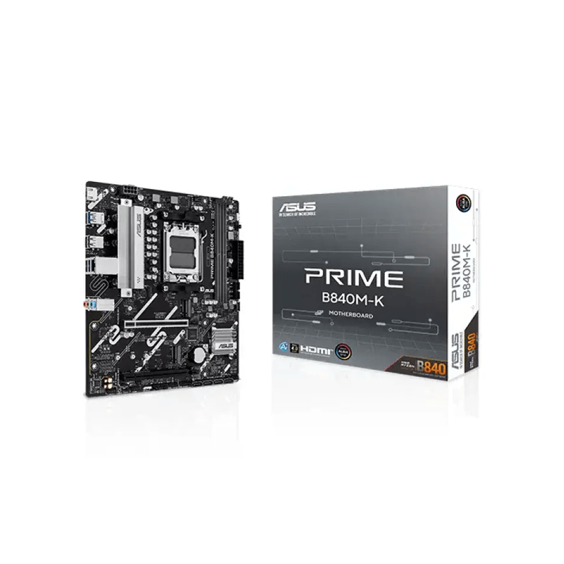
| Micro-ATX (mATX) | 244 × 244 mm | 9.6 × 9.6 in | 3 to 4 slots | 2 or 4 DIMM | Budget builds, compact mid-towers |
| Standard ATX | 305 × 244 mm | 12.0 × 9.6 in | 4 to 7 slots | 4 DIMM | Mid-tower/full-tower gaming & workstations |
| E-ATX (Extended ATX) | 305 × 330 mm | 12.0 × 13.0 in | 4 to 7 slots | 4 to 8 DIMM | High-End Desktop (HEDT), dual-socket servers |
Mounting Hole Patterns and Standoff Placement
A standard ATX motherboard features up to nine mounting holes designed to align with brass standoffs inside a PC chassis. These standoffs ground the printed circuit board (PCB) to the metal chassis frame, preventing electrical shorts and providing mechanical resistance when inserting heavy components like graphics cards or 24-pin power cables.
The standard nine-hole ATX grid is arranged in a 3×3 matrix across the top, middle, and bottom sections of the board:
- Top Row: Located above the CPU socket and VRM heatsinks near the rear I/O.
- Middle Row: Positioned between the CPU socket and the primary PCIe x16 slot.
- Bottom Row: Located along the lower edge near front-panel headers and lower expansion slots.
When installing a motherboard, verifying that every chassis standoff matches an corresponding motherboard mounting hole is critical. An unused standoff left underneath a motherboard can contact exposed trace pathways or solder pads, causing catastrophic short circuits when power is applied.
Electrical Power Delivery: ATX2.x, ATX 3.x, and ATX12VO
Electrical power delivery standards have undergone major structural overhauls to keep pace with modern Graphics Processing Units (GPUs) and CPUs whose instantaneous power draws can spike significantly above their rated Thermal Design Power (TDP).
- Legacy ATX Power Model (ATX 2.x):
- Power Supply provides +3.3V, +5V, +12V, -12V, and +5VSB to the Motherboard via a 24-pin Main Connector Cable.
- Modern ATX12VO Power Model:
- Power Supply provides +12V Only to the Motherboard via a 10-pin Main Connector Cable.
- Motherboard uses Step-down DC-to-DC converters to generate power for SATA Drives and Peripherals.
The Transition from ATX 2.x to ATX 3.0 and ATX 3.1
For nearly two decades, the ATX 2.x power specification governed desktop power supplies (PSUs). Power supplies produced under ATX 2.x output multiple direct voltage rails: +12V (for CPUs and GPUs), +5V and +3.3V (for storage drives and logic circuits), and +5VSB (standby voltage).
However, high-performance graphics architecture introduced severe short-duration power spikes, known as power excursions or transient loads. A GPU rated at 450 Watts could briefly pull 900 Watts or higher for a duration of a few milliseconds, triggering the Over-Current Protection (OCP) or Over-Power Protection (OPP) systems of legacy ATX 2.x power supplies and causing sudden system shut-offs.
To resolve this instability, Intel published the ATX 3.0 Power Supply Design Guide. Key improvements in ATX 3.0 and its successor, ATX 3.1, include:
- Transient Load Excursion Tolerance: ATX 3.0 compliant PSUs must sustain power excursions up to 200% of their rated output power for 100 microseconds.
- 12VHPWR and 12V-2x6 Connectors: Introduction of native 16-pin power cables capable of delivering up to 600 Watts of direct +12V power to PCIe expansion cards over a single cable.
- Sideband Signals: Four signal pins (SENSE0, SENSE1, CARD_PUB, CARD_PWR) allow the power supply and graphics card to communicate dynamic power availability negotiation safely.
The revised 12V-2x6 connector standard introduced under ATX 3.1 shortened the signal pins and lengthened the power pins within the physical connector housing. This physical revision ensures that if a high-power connector is not fully seated into the graphics card, the sense pins fail to make contact, preventing the GPU from drawing high wattage through loose electrical contacts and mitigating thermal melting risks.
The ATX12VO (12V Only) Standard
While ATX 3.1 modernizes traditional multi-rail PSUs, Intel's ATX12VO (12V Only) specification represents a radical departure from legacy desktop power design.
In an ATX12VO platform:
- The power supply converts wall AC power exclusively into a pure +12V DC output rail.
- The legacy 24-pin motherboard connector is replaced by a compact 10-pin main power connector.
- Lower voltage rails (+5V and +3.3V) are eliminated from the PSU entirely. Instead, step-down DC-to-DC voltage converters located directly on the motherboard generate these lower voltages for SATA drives and low-power peripherals.
Advantages and Challenges of ATX12VO
- Energy Efficiency: Removing low-voltage conversion transformers from the power supply dramatically improves energy efficiency during system idle and low-load states, helping manufacturers meet strict international energy conservation regulations.
- Simplified Cabling: PSU cables become thinner and less complex, improving internal case airflow.
- Market Adoption: Despite technical advantages, ATX12VO adoption remains largely confined to pre-built OEM systems (such as Dell, HP, and Lenovo). The DIY retail market continues to favor traditional 24-pin ATX layouts due to backward compatibility with existing components and lower motherboard manufacturing costs.
Key Architectural Components of a Modern ATX Motherboard
Modern ATX motherboards act as complex power-distribution and signal-routing hub systems. The high density of physical space on an ATX PCB allows manufacturers to deploy robust power delivery networks and extensive high-speed expansion interfaces.
- CPU Socket (LGA / AM5)
- 16 to 24 Lanes connecting to PCIe 5.0 x16 Primary GPU Slot
- 4 to 8 Lanes connecting to M.2 PCIe 5.0 NVMe SSD Slot
- Interconnect to System Chipset (PCH)
- PCIe 4.0 Lanes connecting to Secondary PCIe Slots
- SATA III connecting to SATA Ports
- USB4 / USB 3.2 connecting to External I/O Ports
- Interconnect to System Chipset (PCH)
Voltage Regulator Modules (VRM)
The Voltage Regulator Module (VRM) sits adjacent to the CPU socket, usually covered by heavy aluminum heatsinks. The VRM steps down the +12V power received from the PSU's 8-pin EPS connectors to the low voltage required by modern CPUs (typically between 0.8V and 1.4V).
A modern high-end ATX board features multi-phase VRM designs, such as a 16+1+1 phase configuration:
- VCORE Phases (e.g., 16): Supply clean electrical current to the CPU processing cores.
- SOC / VCCSA Phases (e.g., 1): Power the integrated memory controller and system agent.
- MISC Phases (e.g., 1): Provide power to integrated graphics or PCIe bus logic.
Modern VRMs utilize DrMOS (Driver-MOSFET) or integrated power stages that combine the high-side MOSFET, low-side MOSFET, and driver IC into a single silicon package. These power stages are rated in Amperes (e.g., 80A to 105A per phase), allowing enthusiasts to run high-wattage CPUs under sustained all-core workloads without overheating motherboard circuitry.
PCI Express (PCIe) Topology and Signal Integrity
The ATX layout provides structural room for multiple physical PCIe expansion slots. On current platforms, primary lanes originate directly from the CPU socket to minimize latency:
- Primary PCIe x16 Slot: Direct point-to-point connection to the CPU using PCIe 5.0 signaling, yielding up to 64 GB/s of bidirectional bandwidth. These slots feature metal armor reinforcement to support modern, multi-slot graphics cards without physical sagging or PCB tearing.
- Secondary PCIe Slots: Typically routed through the motherboard chipset (Platform Controller Hub or PCH). These slots share available platform bandwidth for sound cards, high-speed networking adapters, or video capture cards.
Due to signal degradation at high frequencies (PCIe 5.0 operates at 32 Gigatransfers per second per lane), board designers utilize low-loss server-grade PCB materials (such as IT-170GRA or Megtron 6) paired with redrivers or retimers to maintain signal integrity across long PCB traces on standard ATX boards.
M.2 NVMe Storage Integration
Modern ATX motherboards feature between three and five onboard M.2 slots for high-speed Solid State Drives (SSDs), bypassing traditional 2.5-inch SATA cables entirely.
- Direct CPU-attached M.2: The top M.2 slot routes directly to the CPU's dedicated storage lanes, supporting PCIe 5.0 x4 speeds (up to ~14,000 MB/s sequential read throughput).
- Thermal Management: PCIe 5.0 NVMe SSD controllers operate at elevated temperatures under continuous load. Standard ATX boards integrate dedicated aluminum heat spreaders and multi-layer thermal pads across all M.2 slots to prevent thermal throttling.
Rear I/O Architecture and Connectivity
The integrated rear I/O panel of a modern ATX motherboard standardizes external device connectivity:
- High-Speed USB and Thunderbolt: Integration of USB4 standards and Thunderbolt 4/5 interfaces delivering up to 40-80 Gbps throughput alongside DisplayPort Alt-Mode output.
- Networking Infrastructure: Built-in 2.5 Gigabit or 10 Gigabit Ethernet controllers (e.g., Intel I226-V, Marvell AQtion), paired with integrated Wi-Fi 7 (802.11be) modules operating on 2.4 GHz, 5 GHz, and 6 GHz spectrum bands.
- Audio Shielding: Physical isolation of the audio processing circuitry from the rest of the PCB to minimize Electromagnetic Interference (EMI), often employing high-end Digital-to-Analog Converters (DACs) and specialized audio capacitors.
Building with ATX: Compatibility and Case Selection
Selecting an ATX motherboard requires systematic verification of structural clearances, power infrastructure, and cooling configurations.
Mid-Tower ATX Chassis Layout:
- Top AIO Radiator Mount: 360mm
- Rear Exhaust Fan: 120mm / 140mm
- Motherboard CPU Socket: Air Cooler / Liquid Block
- Triple-Slot GPU: Length Clearance Check up to 400mm
- Power Supply Shroud: ATX3.1 PSU with Direct 12V-2x6 Native Routing
Chassis Clearance Rules
While any standard mid-tower or full-tower chassis designated as "ATX Compatible" will physically accept the 305 × 244 mm mounting pattern, specific hardware dimensions demand careful measurement:
- CPU Cooler Height: Heavy dual-tower air coolers often stand between 155 mm and 165 mm tall. Ensure the chassis width accommodates this height clearance off the CPU IHS (Integrated Heat Spreader).
- GPU Clearance and Cable Bending Radius: Modern high-end GPUs often exceed 340 mm in length and 140 mm in height. Crucially, when using 16-pin (12V-2x6 / 12VHPWR) power cables, maintain at least 30 mm of unbent cable clearance between the GPU power socket and the side panel glass to avoid terminal stress and connector overheat.
- Radiator Top/Front Mounting: Installing liquid cooling All-In-One (AIO) radiators (e.g., 280mm or 360mm) requires checking clearance relative to high VRM heatsinks and tall DDR5 RAM modules at the top edge of the motherboard.
Back-Connect Motherboards (BTF / Project Zero)
A major mechanical design shift within the ATX ecosystem is the introduction of rear-facing connector motherboards (commercially designated under initiatives like ASUS BTF or MSI Project Zero).
On a back-connect ATX motherboard:
- The 24-pin ATX power connector, EPS 8-pin CPU power ports, SATA channels, fan headers, and front-panel pins are moved to the back surface of the PCB.
- The front face of the board presents a clean, cable-free aesthetic with exposed heatsinks and PCIe slots.
Compatibility Warning: Back-connect ATX motherboards do not fit in traditional ATX chassis. They require specialized cases manufactured with dedicated mechanical cutouts along the motherboard mounting tray to allow access for rear-plugged cables.
Practical Troubleshooting and Maintenance
Proper installation and maintenance prevent common system stability issues associated with ATX platforms.
Step-by-Step Installation Procedure
- Prepare the Chassis: Thread brass standoffs precisely into the nine standard ATX mounting points inside the chassis tray. Remove any extra standoffs that do not match your board.
- Install Core Components First: Seat the CPU, install M.2 storage drives (under their heatsinks), and insert DDR5 RAM into the recommended primary channels (typically slots A2 and B2) before placing the motherboard into the chassis.
- Mount Motherboard: Align the motherboard rear I/O with the case cutout and lower the board gently onto the standoffs. Secure the board using standard 6-32 threaded screws, tightening in a cross-pattern until snug. Do not overtighten, as this can fracture PCB copper traces.
- Connect Power: Plug in the primary 24-pin cable (or 10-pin for ATX12VO) and the dual 8-pin EPS CPU power cables. Ensure the plastic retaining latches click completely into position.
- Install Expansion Cards: Insert the GPU into the primary CPU-attached PCIe x16 slot until the retention latch snaps locked. Fasten the expansion bracket to the chassis frame using case screws.
Troubleshooting Diagnostic Indicators
Modern ATX motherboards incorporate built-in diagnostic tools to isolate hardware boot failures (POST failures):
- EZ Debug LEDs: Four labeled LEDs (CPU, DRAM, VGA, BOOT) illuminate sequentially during startup. If the boot process halts, the active LED identifies the failing component subgroup.
- Two-Digit Q-Code Display: Premium ATX motherboards include a hexadecimal LED readout that displays specific initialization codes. Consult the motherboard manual's code table to diagnose granular issues (e.g., Code
55indicates uninitialized RAM, often caused by poor memory contact or bent CPU socket pins).
Frequently Asked Questions
Can a Micro-ATX motherboard be installed in a standard ATX case?
Yes. Micro-ATX (mATX) boards share the same top six mounting hole positions and I/O spacing as standard ATX motherboards. Nearly all mid-tower and full-tower ATX cases include pre-drilled standoff locations to accept Micro-ATX motherboards without requiring modification.
What is the difference between ATX 3.0 and ATX 3.1 power supplies?
ATX 3.1 is an incremental update to the ATX 3.0 power supply design guideline. The primary modification is the replacement of the original 12VHPWR high-power GPU connector with the revised 12V-2x6 connector. The 12V-2x6 standard shortens the four signal sense pins and extends the electrical power pins, ensuring that high power cannot be delivered unless the cable is fully inserted, thereby improving safety and thermal stability.
What happens if I do not plug in the secondary 8-pin CPU power connector?
Most desktop CPUs will function normally with only one 8-pin EPS power connector attached, as a single 8-pin cable can deliver up to 336 Watts of continuous +12V power. However, connecting both 8-pin connectors is strongly recommended when running high-draw flagship processors or conducting manual CPU overclocking to distribute electrical current across multiple cables, reducing resistance and heat buildup at the PSU terminal junctions.
What is E-ATX, and will an E-ATX board fit in a standard ATX case?
Extended ATX (E-ATX) is broader than standard ATX, typically measuring 12 × 13 inches (305 × 330 mm) compared to standard ATX's 12 × 9.6 inches (305 × 244 mm). While E-ATX boards use the same vertical mounting pin locations, they extend horizontally to the right. Standard ATX mid-tower cases often lack room for this extra width, as the board may cover internal cable-pass-through grommets or collide with drive cages. An E-ATX specific or wide mid/full-tower chassis is recommended.
How do I know if my power supply is compatible with my ATX motherboard?
Standard ATX motherboards require a power supply that provides a 24-pin ATX Main Connector (or a 20+4 pin variant) alongside at least one 8-pin (4+4 pin) EPS CPU connector. Check your processor's power requirements and motherboard manual: high-performance motherboard designs usually require two 8-pin EPS connectors. If using modern high-power graphics cards, select an ATX 3.0 or ATX 3.1 power supply equipped with a native 12V-2x6 cable.
Final Recommendation and Buyer Guidance
When building or upgrading a desktop PC system, matching component selection to your architectural performance requirements ensures long-term system stability:
- For General Enthusiasts and Gamers: Choose a standard ATX motherboard paired with an ATX 3.1 power supply. This combination offers the best balance of expansion room, robust VRM cooling, thermal pad coverage for multiple PCIe 4.0/5.0 NVMe drives, and native power support for high-end graphics cards.
- For Cable-Managed Showcase Builds: If selecting a back-connect (BTF/Project Zero) motherboard, verify chassis compatibility explicitly against the case manufacturer's approved motherboard support list before purchase.
- Installation Checklist: Always confirm standoff alignments, fully seat all 16-pin 12V-2x6 graphics connectors until the latch clicks, and install RAM modules in dual-channel configurations (slots A2/B2) for optimal system performance.