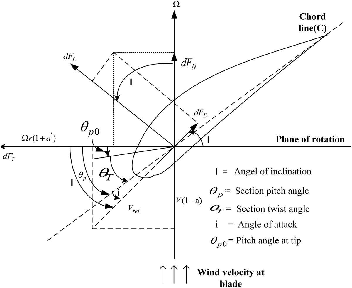
The angle of incidence is the fixed geometric angle formed between the chord line of an aircraft wing and its longitudinal axis. Unlike the dynamic angle of attack, this structural parameter is engineered directly into the airframe to optimize cruise efficiency, minimize fuselage parasite drag, maintain pilot forward visibility, and control stall behavior across the wingspan.
Defining Angle of Incidence vs. Angle of Attack
In aeronautical engineering, confusing the angle of incidence with the angle of attack (AOA) is a common misconception. While both parameters dictate how an airfoil interacts with airflow, their physical definitions, control mechanisms, and flight operational roles are fundamentally distinct.
The Geometric Definition of Angle of Incidence
The angle of incidence (often abbreviated as AOI or referred to as the wing setting angle) is a static, structural angle set during the design and manufacturing of the airframe.
To measure the angle of incidence:
- Identify the longitudinal axis of the aircraft—an imaginary reference line running straight from the tip of the nose cone through the center of gravity to the tail tip.
- Draw the chord line of the wing airfoil at a given spanwise station—the straight line connecting the leading edge directly to the trailing edge.
- The acute angle formed between this longitudinal reference line and the chord line represents the angle of incidence.
Because it is built into the airframe structure, the angle of incidence on most conventional fixed-wing aircraft cannot be altered by pilot control inputs during flight. It remains constant regardless of whether the aircraft is climbing, banking, descending, or sitting on the tarmac.
- Longitudinal Axis of Fuselage
- Angle of Incidence
- Chord Line of Wing Airfoil
Why Angle of Attack Differs: Dynamic vs. Fixed Geometry
In contrast to the fixed angle of incidence, the angle of attack is a dynamic aerodynamic state. It is defined as the angle between the wing's chord line and the vector of the relative wind (the directional pathway of oncoming air relative to the aircraft's motion).
- Control: The pilot dynamically alters the angle of attack using flight controls (primarily the elevators or stabilators) to pitch the nose up or down.
- Variability: AOA constantly shifts based on airspeed, aircraft weight, flight maneuver load factors, and vertical atmospheric gusts.
- Relationship: The angle of incidence directly establishes the baseline angle of attack that the wing experiences when the fuselage is flying at zero pitch attitude relative to the flight path vector.
Aerodynamic Objectives and Structural Mechanics of Wing Incidence
Aircraft designers do not attach wings parallel to the fuselage axis (zero degree angle of incidence) without strategic cause. Engineering a positive angle of incidence serves several primary aerodynamic and operational functions that directly enhance mission performance.
Fuselage Alignment and Parasite Drag Optimization in Cruise
During steady-state level cruise—which constitutes the vast majority of a commercial or general aviation aircraft's flight profile—the wing must generate sufficient lift ($L$) to balance the aircraft's total gross weight ($W$). Generating this required lift requires the wing airfoil to operate at a positive coefficient of lift ($C_L$), which inherently requires a positive angle of attack relative to incoming relative wind.
If an aircraft were built with a $0^\circ$ angle of incidence:
- To maintain the required positive angle of attack for level flight, the pilot would have to pitch the entire airframe nose-up.
- Flying with the fuselage pitched upward relative to the flight path substantially increases the fuselage's frontal surface area presented to oncoming air.
- This pitch attitude creates massive amounts of parasite drag (specifically form drag and pressure drag), significantly increasing fuel burn and reducing overall range.
By setting the wing at a positive angle of incidence (typically between $2^\circ$ and $6^\circ$ depending on the aircraft type and wing profile), the wing achieves its optimal cruise angle of attack while the fuselage remains aligned parallel to the airflow. This reduces airframe parasite drag to its absolute theoretical minimum during high-speed cruise conditions.
Pilot Forward Visibility and Cockpit Ergonomics
Fuselage attitude directly impacts pilot ergonomics and field of view. When an aircraft approaches an airport for landing or climbs after takeoff, high angles of attack are required due to lower airspeeds.
If the angle of incidence were non-existent or negative, the required nose-up pitch attitude during approach would block the pilot's view of the runway over the glare shield. Designing the wing with an appropriate positive angle of incidence allows the airframe to fly its approach glide path at a lower fuselage pitch angle, maintaining unobstructed forward vision of visual slope indicators and runway markings.
Variable Incidence Across the Span: Washout and Twist Engineering
The angle of incidence is rarely uniform from the wing root (where the wing joins the fuselage) to the wing tip. Aircraft designers implement geometric twist, commonly known as aerodynamic washout, by varying the angle of incidence along the span.
Aerodynamic Washout Mechanics
In a wing designed with washout:
- The wing root is set to the highest positive angle of incidence (e.g., $+4^\circ$).
- The incidence progressively decreases along the span toward the outer wing sections.
- The wing tip is set to a lower angle of incidence, or sometimes even a slightly negative angle relative to the root (e.g., $+1^\circ$ or $0^\circ$).
This structural variation guarantees that during any flight maneuver, the local angle of attack at the wing root is higher than the local angle of attack at the wing tip.
- Wing Root: High Angle of Incidence (+4°) – Reaches Critical AOA First (Stalls First)
- Progressive Geometric Twist / Washout
- Wing Tip: Low Angle of Incidence (+1°) – Operates Below Critical AOA (Remains Unstalled)
Preventing Tip Stall and Preserving Roll Control
Washout is a fundamental safety feature designed to prevent catastrophic loss of control during high-AOA maneuvers or slow-flight conditions:
- Root-First Stall Propagation: As the aircraft pitches up and reaches the critical angle of attack, airflow separation occurs first at the wing root.
- Early Stall Warning: Airflow breakdown at the root creates turbulent wake buffers that strike the horizontal tail, providing physical buffet feedback through the control column before full-wing stall occurs.
- Preservation of Roll Control: Because the wing tips operate at a lower angle of incidence, the outer span remains completely unstalled when the root begins to stall. Since ailerons are located near the wing tips, the pilot retains complete lateral roll control to steady the wings and recover from the stall safely.
Without geometric washout, outboard wing sections could stall first ("tip stall"). Tip stalls frequently trigger aggressive asymmetrical rolling moments, leading to uncontrollable wing drops or entry into developed spins.
Flight Impact: How Angle of Incidence Governs Performance Parameters
The choice of wing incidence angle affects almost every phase of flight, governing performance vectors from fuel consumption efficiency to low-speed handling characteristics.
Cruise Efficiency and Specific Fuel Consumption
In long-range transport aircraft, operating at peak aerodynamic efficiency—expressed as the maximum lift-to-drag ratio ($(L/D)_{\max}$)—is essential for economic performance.
The angle of incidence is selected to match the airframe's target cruise Mach number and nominal operating weight. If the incidence angle is miscalculated during design:
- Excessive Incidence: The fuselage flies nose-down in cruise, generating trim drag, nose drag, and excessive upper-fuselage flow separation.
- Deficient Incidence: The fuselage flies nose-up in cruise, raising lower-surface drag, increasing trim drag from the horizontal stabilizer, and reducing passenger cabin comfort.
Properly optimized incidence ensures that the wing operates precisely at its maximum $L/D$ point while the cabin floor remains level, optimizing fuel efficiency and cabin ergonomics simultaneously.
Stall Dynamics and Longitudinal Trim Stability
The wing's angle of incidence directly interacts with the tailplane's setting angle, establishing the overall longitudinal static stability of the airframe:
- Downwash Effects: The incidence of the wing alters the direction of air flowing off its trailing edge (downwash). This downwash impinges directly on the horizontal stabilizer.
- Trim Drag Minimization: Designers match the main wing incidence with the horizontal tail incidence so that at cruise speeds, the tail needs minimal elevator deflection to hold the aircraft in longitudinal balance. Minimizing required elevator deflection direct minimizes overall trim drag.
Takeoff and Landing Performance Characteristics
During the takeoff roll, an aircraft accelerates along the runway with all landing gear wheels on the pavement.
- Ground-Roll Lift Generation: An aircraft with a positive angle of incidence generates a baseline amount of lift while rolling flat on its landing gear without requiring immediate control inputs.
- Rotation Dynamics: When the pilot reaches rotation speed ($V_R$) and pulls back on the yoke, the aircraft rotates around its main gear. The built-in incidence provides a head start on lift generation, shortening the ground roll distance needed to achieve lift-off.
Conversely, if an aircraft has zero incidence, the wing produces minimal lift during ground travel until substantial pitch rotation occurs, requiring longer runways and higher rotation force.
Comparative Engineering Matrix: Airfoil Geometry and Incidence Configurations
The optimal angle of incidence depends heavily on the aircraft's mission envelope, wing sweep, structural layout, and target operational airspeeds.
| Aircraft Class / Design Type | Typical Root Incidence Angle | Typical Tip Incidence (Washout) | Primary Aerodynamic Objective | Operational Trade-offs |
|---|---|---|---|---|
| General Aviation Training (e.g., Cessna 172) | $+3.5^\circ$ to $+4.0^\circ$ | $+1.0^\circ$ to $+1.5^\circ$ (Washout: $2.5^\circ$) | Maximum stall warning, high roll authority at low speeds, level nose attitude during training maneuvers. | Slightly higher parasite drag penalty at high-speed cruise dashes. |
| Commercial Turboprops (e.g., ATR 72, Dash 8) | $+3.0^\circ$ to $+5.0^\circ$ | $+0.5^\circ$ to $+1.5^\circ$ (Washout: $3.0^\circ$) | Efficient short-field takeoff/landing performance, low pitch attitude on visual approach paths. | Increased airframe interference drag at wing-fuselage fairing junctions. |
| High-Subsonic Jet Transport (e.g., Boeing 737 / Airbus A320) | $+1.0^\circ$ to $+3.0^\circ$ | $-0.5^\circ$ to $+0.5^\circ$ (Variable Aero Twist) | Maximum $(L/D)_{\max}$ at Mach 0.78–0.82, optimum cabin floor angle during long-range cruise. | High rotation angles required during takeoff; critical tail-strike protection limits. |
| Supersonic Military Fighters (e.g., F-16, F-15) | $0.0^\circ$ to $+1.0^\circ$ | Minimal geometric twist ($0.0^\circ$) | Minimal wave drag at supersonic speeds; symmetric inverted flight capabilities. | High angle of attack required during approach; heavy reliance on automated flight control systems (fly-by-wire). |
| Aerobatic Aircraft (e.g., Extra 330) | $0.0^\circ$ | $0.0^\circ$ (Zero Twist) | Identical handling, lift, and stall behavior in both upright and inverted flight modes. | Demands continuous pilot pitching inputs; higher stall speed; aggressive wing tip drop tendencies. |
Specialized Applications and Historical Case Studies
While the majority of fixed-wing aircraft utilize a fixed, non-adjustable angle of incidence, structural variations and specialized mechanisms exist across aviation history to solve specific flight regime challenges.
Variable-Incidence Mechanisms: The F-8 Crusader
One of the most notable engineering implementations of an adjustable incidence angle is the Vought F-8 Crusader, a carrier-based supersonic fighter developed in the 1950s for the U.S. Navy.
Vought F-8 Crusader Mechanism:
Normal Flight: Wing sits flush with fuselage (0° Incidence for high speed)
Takeoff/Landing: Wing pivots upward 7° via hydraulic actuator
- Increases Wing Angle of Attack for maximum lift
- Keeps Fuselage Level for Pilot Approach Visibility
- Lowers Landing Gear Angle relative to deck
The Carrier Landing Problem: High-performance swept wings require high angles of attack to generate sufficient lift at slow landing approach speeds. However, pitching the entire airframe up on approach would severely limit pilot visibility over the nose and require exceptionally long, heavy main landing gear struts to prevent tail strikes on the carrier deck.
The Variable-Incidence Solution: Designers implemented a hydraulic system that pivoted the entire main wing assembly upward by $7^\circ$ at the leading edge during takeoff and landing.
Operational Result: The wing achieved the high angle of attack necessary for low-speed lift generation while the fuselage remained almost level. This design optimized visibility over the carrier deck nose ramp while keeping landing gear weight low.
High-Wing vs. Low-Wing Structural Configurations
The physical mounting location of the wing relative to the fuselage alters how the angle of incidence is integrated structurally:
- High-Wing Layouts: High-wing aircraft (such as the Cessna 208 Caravan or military transports like the C-130 Hercules) generally experience less ground effect interference during landing and benefit from pendulum stability. The angle of incidence is engineered to allow the large payload fuselage to hang level, optimizing cargo deck loading and air-drop ops.
- Low-Wing Layouts: Low-wing aircraft feature wing roots that pass through or underneath the main carry-through spar structure. The angle of incidence must be carefully integrated with the wing root fairings to prevent flow separation in the acute corner between the upper wing surface and the curved fuselage wall—a phenomenon managed by using specialized fillet fairings and localized incidence adjustments.
Key Engineering Considerations for Aircraft Designers and Pilots
For Aircraft Designers: Balancing Trade-offs
Establishing the angle of incidence requires balancing several competing performance demands:
- Mission Profile Centering: Designers choose the primary operating point (e.g., long-range cruise speed, altitude, payload). The angle of incidence is matched to this specific flight state to align the airframe for minimal drag.
- Wing-Root Intersections: High incidence angles create steep pressure gradients where the wing upper surface meets the fuselage, requiring complex aerodynamic fairings to avoid localized flow separation.
- Weight Penalties: Complex geometries like variable incidence add structural weight and hydraulic complexity, which is why modern transport aircraft rely instead on trailing-edge flaps and leading-edge slats to vary camber and lift dynamically.
For Aviators: Operational Takeaways
While pilots cannot adjust a fixed angle of incidence mid-flight, understanding its operational implications enhances airmanship:
- Attitude Reference: In cruise, if the attitude indicator shows a noticeable nose-high or nose-down pitch angle while maintaining altitude, the aircraft is operating away from its design optimum (e.g., flying too slow or heavily overloaded), causing the airframe to fly out of alignment with the airflow.
- Stall Behavior: Recognizing that geometric washout causes the wing root to stall before the tips helps pilots interpret early stall warnings (buffeting) while maintaining confidence in roll control via the ailerons.
- Ground Operations: Understanding built-in incidence clarifies why some aircraft generate lift quickly during takeoff rolls even with minimal control stick deflection.
Frequently Asked Questions
Can the angle of incidence change during flight?
On almost all modern aircraft, the angle of incidence is fixed permanently into the airframe structure and cannot change during flight. However, rare specialized aircraft, such as the historic Vought F-8 Crusader, used mechanical actuators to pivot the wing structural assembly up and down for takeoff and landing. Variable-sweep aircraft (like the F-14 Tomcat) alter wing sweep, but their structural angle of incidence relative to the wing pivot axis remains set.
How does angle of incidence affect stall speed?
The angle of incidence does not directly change an aircraft's unaccelerated stall speed, because stall speed depends on maximum lift coefficient ($C_{L,\max}$), total aircraft weight, wing surface area, and air density. However, because incidence determines how early different parts of the wing reach their critical angle of attack, geometric variation in incidence (washout) ensures that the stall progresses smoothly from root to tip rather than occurring abruptly across the entire wing.
Is angle of incidence the same as wing dihedral?
No. The angle of incidence is measured in the longitudinal plane (side view) between the chord line and the fuselage centerline. Dihedral is measured in the frontal plane (front view) and represents the upward angle of the wings relative to the horizontal plane. While incidence optimizes cruise lift, drag, and trim attitude, dihedral provides lateral (roll) stability when the aircraft slips or skids.
Why do some aerobatic airplanes have a zero angle of incidence?
Aerobatic airplanes engineered for competition (such as the Extra 330 or Pitts Special) often utilize a $0^\circ$ angle of incidence paired with a symmetrical airfoil and zero wing washout. This allows the aircraft to perform identically whether flying right-side-up or inverted, ensuring predictable control responses and lift characteristics in all orientations.
What is the difference between geometric washout and aerodynamic washout?
Geometric washout is the physical variation of the wing's angle of incidence along its span, where the wing tip is physically twisted downward relative to the root. Aerodynamic washout achieves a similar effect without physical twisting by altering the airfoil profile shape along the span—such as using a thinner or lower-camber section at the tip—so that the wing root still reaches its stall point before the tip does.
Operational Summary and Design Recommendations
When reviewing or evaluating airfoil design specifications, keep the following core engineering principles in mind:
- Distinguish Geometry from Dynamics: Treat the angle of incidence as a fixed airframe design parameter that establishes structural alignment, and the angle of attack as the dynamic fluid-dynamic parameter managed via elevator inputs.
- Prioritize Fuselage Alignment: Ensure the selected baseline angle of incidence aligns the fuselage parallel to cruise airflow at target Mach numbers to minimize parasite form drag and optimize fuel economy.
- Incorporate Washout for Safety: Verify that fixed-wing geometries feature sufficient spanwise reduction in incidence (washout) to guarantee root-first stall propagation, protecting aileron control authority during low-speed maneuvers.
- Account for Trim Drag: Balance main wing incidence alongside horizontal tail incidence to minimize required elevator deflections during long-range cruise conditions.