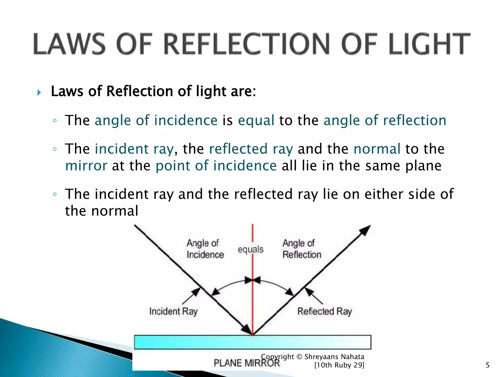
The law of reflection states that when a ray of light strikes a surface, the angle of incidence is strictly equal to the angle of reflection. Both angles are measured between the light rays and an imaginary perpendicular line called the normal, drawn at the point of contact, with all three existing within a single geometric plane.
Understanding the Geometry of Light Reflection
To understand how light behaves when it interacts with boundaries, physicists rely on geometric optics. Geometric optics models light as narrow streams of energy called light rays. When light propagates through a uniform medium, it travels in straight lines until it encounters an interface between two different materials or surfaces. At this boundary, several optical phenomena can occur: reflection, refraction, absorption, or scattering.
Reflection occurs when light bounces off a boundary back into the original medium rather than passing through it or being converted into thermal energy. To analyze this interaction accurately, precise geometric reference points must be established.
- Incident Ray: Incoming light ray approaching the point of incidence, forming the Angle of Incidence ($\theta_i$) relative to the normal line.
- Normal Line: Imaginary line perpendicular (90 degrees) to the surface drawn at the point of incidence.
- Reflected Ray: Outgoing light ray moving away from the point of incidence, forming the Angle of Reflection ($\theta_r$) relative to the normal line.
- Surface: The reflective boundary containing the Point of Incidence.
Defining the Ray Model of Light
The ray model is a mathematical simplification that represents the path of light as a straight line vector directed along the beam's propagation direction. While light fundamentally exhibits wave-particle duality, behaving as both electromagnetic waves governed by Maxwell's equations and discrete photons, the ray approximation is valid whenever the physical features of the reflecting surface are substantially larger than the light's wavelength.
For visible light, which spans wavelengths roughly between 380 nanometers (violet) and 750 nanometers (red), everyday surfaces like glass windows, polished metals, and still water meet this condition easily. The ray approach provides a precise method for calculating trajectory, image location, and optical system paths without the mathematical complexity of wave diffraction equations.
The Normal Line: The Critical Reference Boundary
The most essential reference line in geometric optics is the normal line (often referred to simply as the normal). The normal is an imaginary construction line drawn perpendicular (at a 90-degree angle) to the reflecting surface at the exact location where the incident light ray strikes—known as the point of incidence.
Measuring optical angles relative to the surface itself introduces ambiguity, especially when dealing with curved mirrors, irregular topography, or non-planar boundaries. By measuring all angles relative to the normal:
- Every geometry, whether flat, spherical, parabolic, or irregular, uses a consistent, localized coordinate system.
- Calculations across flat mirrors, convex lenses, optical fibers, and complex camera lenses remain mathematically standardized.
Quantifying the Angle of Incidence and Angle of Reflection
Two primary angles define the geometry of a reflective event:
- Angle of Incidence ($\theta_i$ or $i$): The angle formed between the incoming (incident) light ray and the normal line at the point of incidence.
- Angle of Reflection ($\theta_r$ or $r$): The angle formed between the outgoing (reflected) light ray and the normal line at the point of incidence.
A common beginner mistake is measuring these angles between the light ray and the surface plane itself. In formal optics, the surface angle is known as the glancing angle ($\alpha$), which equals $90^\circ - \theta_i$. Standard physics equations, including Snell's Law and Fresnel reflection coefficients, require angles measured strictly relative to the normal.
The Law of Reflection: Core Principles and Mathematical Formulation
The fundamental behavior of reflecting light is governed by the Law of Reflection. Derived experimentally by Hero of Alexandria in antiquity and later proven mathematically through electromagnetic theory, the law consists of two mandatory conditions.
The Two Statements of the Law of Reflection
- Equal Angle Condition: The angle of reflection is identically equal to the angle of incidence. $$\theta_i = \theta_r$$
- Coplanarity Condition: The incident ray, the reflected ray, and the normal line all lie within the same two-dimensional plane, known as the plane of incidence.
If an incident ray strikes a flat mirror at an angle of $30^\circ$ to the normal line, the reflected ray exits at exactly $30^\circ$ relative to that same normal line on the opposite side, sharing the plane established by the incident ray and the normal.
- Incident Ray: Enters at an angle of incidence $\theta_i = 30^\circ$ relative to the normal line.
- Normal Line: Perpendicular reference line at the point of incidence.
- Reflected Ray: Exits at an angle of reflection $\theta_r = 30^\circ$ relative to the normal line.
- Reflective Surface: Boundary interface where the ray strikes.
Theoretical Foundations: Fermat’s Principle and Huygens’ Principle
Why does light obey this precise geometric equality? Two classical frameworks explain this fundamental behavior:
Fermat's Principle of Least Time
Formulated by French mathematician Pierre de Fermat in 1662, this principle states that light traveling between two points follows the path that requires the shortest time. When light travels from a source point $A$, reflects off a planar boundary, and travels to a destination point $B$ within a uniform medium (where speed $v = c/n$ is constant), minimizing travel time is identical to minimizing total distance.
Using basic calculus to find the minimum distance path along a planar mirror demonstrates that the shortest path occurs exclusively when the angle of incidence equals the angle of reflection.
Huygens' Principle
Proposed by Christiaan Huygens in 1678, this wave theory approach treats every point on a propagating wavefront as a source of secondary spherical wavelets. When a planar wavefront strikes a reflective interface at an angle, different points along the wavefront reach the boundary at sequential times.
The envelope of the secondary wavelets expanding back into the original medium forms a new planar wavefront traveling away from the surface. The geometry of these expanding wavelets enforces the condition that the incoming wavefront angle matches the outgoing wavefront angle relative to the interface.
Specular vs. Diffuse Reflection: Surface Topography and Light Behavior
While the law of reflection holds true for every individual photon and ray at the microscopic level, the overall macroscopic behavior of reflected light depends heavily on the surface texture.
- Specular Reflection:
- Incoming Light: Parallel incoming rays.
- Surface: Smooth surface.
- Outcome: Rays stay parallel, resulting in a clear reflection.
- Diffuse Reflection:
- Incoming Light: Parallel incoming rays.
- Surface: Microscopically rough surface.
- Outcome: Rays scatter in many directions.
Specular (Regular) Reflection
Specular reflection occurs when light strikes a smooth, polished surface where surface irregularities are significantly smaller than the wavelength of the incoming light (typically less than $\lambda/8$).
- Behavior: Parallel incoming light rays remain parallel after reflection.
- Visual Result: The surface produces a clear, distinct mirror image of the light source and surrounding environment.
- Common Examples: Highly polished silver or aluminum mirrors, calm water surfaces, smooth glass panes, and glossy car finishes.
Because the surface normals across a flat, polished plane are all parallel to one another, identical incident angles produce identical reflected angles across the entire beam.
Diffuse (Irregular) Reflection
Diffuse reflection occurs when light strikes an unpolished, rough, or textured surface containing microscopic peaks, troughs, and irregular slopes larger than the wavelength of light.
- Behavior: Parallel incoming light rays hit regions with different normal orientations. Even though $\theta_i = \theta_r$ at every specific microscopic point of contact, the varying local normals reflect the rays in diverse directions.
- Visual Result: Light is scattered uniformly across space. No reflected image is formed, but the surface itself becomes visible from virtually any viewing angle.
- Common Examples: Matte paper, dry soil, unpolished wood, natural fabrics, and wall paint.
Without diffuse reflection, non-luminous everyday objects would be invisible unless viewed directly along a mirror-reflection path. Diffuse scattering distributes ambient light throughout spaces, enabling human vision and camera sensors to perceive forms, textures, and depth.
Comprehensive Comparison: Reflection Types and Optical Phenomena
The table below contrasts specular and diffuse reflection along with related optical interface phenomena.
| Characteristic / Feature | Specular Reflection | Diffuse Reflection | Refraction (Snell's Law) | Total Internal Reflection |
|---|---|---|---|---|
| Surface Condition | Smooth / Polished (roughness $< \lambda$) | Rough / Textured (roughness $> \lambda$) | Transparent boundary ($n_1 \neq n_2$) | Optics interface ($n_1 > n_2$) |
| Normal Consistency | Uniformly parallel across surface | Variable localized orientation | Uniform or defined across boundary | Uniform boundary plane |
| Ray Path Alignment | Parallel rays stay parallel | Parallel rays scatter in many directions | Rays bend entering new medium | Rays reflect entirely into initial medium |
| Image Formation | Clear virtual or real images formed | No distinct image; visible texture | Shifted or distorted image | High-efficiency mirror reflection |
| Governing Equation | $\theta_i = \theta_r$ | $\theta_i = \theta_r$ (microscopic local) | $n_1 \sin\theta_1 = n_2 \sin\theta_2$ | $\theta_c = \arcsin(n_2/n_1)$ |
| Primary Real-World Use | Mirrors, telescopes, periscopes | Ambient room light, projection screens | Lenses, eyeglasses, camera optics | Fiber optic communication |
Transitioning from Reflection to Refraction: Snell’s Law and Interface Optics
When light strikes a boundary separating two transparent optical media—such as air and glass or water and air—reflection is rarely the only outcome. Instead, the incident light energy splits at the interface: a portion reflects back into the primary medium while the remainder transmits into the second medium.
- Medium 1 ($n_1$):
- Incident Ray: Light ray traveling in Medium 1 toward the boundary.
- Reflected Ray: Light ray reflected back into Medium 1, where $\theta_r = \theta_i$.
- Normal: Perpendicular reference line passing through the interface between both media.
- Medium 2 ($n_2$):
- Refracted Ray: Light ray transmitted into Medium 2 at angle $\theta_t$, bending toward or away from the normal line.
Snell's Law and Refraction Mechanics
The portion of light that passes into the second medium changes speed due to the change in optical density (quantified by the refractive index, $n$). This change in propagation speed causes the light ray to bend, a process called refraction.
Refraction is governed by Snell's Law (the Law of Refraction): $$n_1 \sin(\theta_1) = n_2 \sin(\theta_2)$$
Where:
- $n_1$ and $n_2$ are the absolute refractive indices of the first and second media.
- $\theta_1$ is the angle of incidence (measured relative to the normal).
- $\theta_2$ is the angle of refraction (measured relative to the normal in the second medium).
When light travels from an optically rarer medium to a denser medium ($n_2 > n_1$), such as from air ($n \approx 1.0003$) into crown glass ($n \approx 1.52$), the refracted ray bends toward the normal line ($\theta_2 < \theta_1$). Conversely, when moving from a denser to a rarer medium ($n_1 > n_2$), the light bends away from the normal.
Total Internal Reflection and Critical Angles
When light travels from a medium of higher refractive index toward one of lower refractive index ($n_1 > n_2$), increasing the angle of incidence causes the refracted angle $\theta_2$ to approach $90^\circ$.
The specific angle of incidence where the refracted ray travels parallel to the boundary interface ($\theta_2 = 90^\circ$) is called the critical angle ($\theta_c$): $$\theta_c = \arcsin\left(\frac{n_2}{n_1}\right)$$
If the angle of incidence exceeds the critical angle ($\theta_i > \theta_c$), light can no longer refract into the second medium. Instead, 100% of the incident light energy reflects back into the higher-index medium. This phenomenon is known as Total Internal Reflection (TIR).
TIR forms the operational foundation of modern fiber optic cables, medical endoscopes, and high-precision glass prisms used in binoculars. Additional technical literature on wave propagation and electromagnetic interface boundary conditions is available through the National Institute of Standards and Technology (NIST) Physics Laboratory.
Practical Applications of Reflection Principles
The simple rule $\theta_i = \theta_r$ underpins advanced scientific instruments, industrial processes, and consumer technologies.
Optical Instruments and Telescopes
Reflecting Telescopes (Catoptrics)
Large astronomical telescopes, including the James Webb Space Telescope and the Keck Observatory, rely on curved mirrors rather than refractive lenses. Large glass lenses tend to sag under their own weight and suffer from chromatic aberration (color distortion caused by different wavelengths refracting at slightly different angles).
By shaping mirrors into precise parabolic geometries, optical engineers ensure that all parallel light rays arriving from distant stars hit the mirror surface at calculated angles of incidence, reflecting them to a single focal point.
- Parabolic Mirror Focusing Parallel Light Rays:
- Incoming Rays: Parallel light rays travel toward the parabolic mirror.
- Parabolic Mirror Surface: Reflects incoming parallel rays according to calculated local incident angles.
- Focal Point (F): All reflected light rays converge at a single focal point.
Periscopes and Rangefinders
Submarine periscopes and military rangefinders use pairs of flat mirrors or right-angle total internal reflection prisms positioned at $45^\circ$ angles relative to the line of sight. An incident light ray striking the first mirror at $\theta_i = 45^\circ$ reflects at $\theta_r = 45^\circ$, turning the beam by $90^\circ$. A second mirror reverses the turn, allowing observers to see over obstacles safely.
Fiber Optics and Telecommunications
Modern global telecommunications rely on glass optical fibers to carry data as light pulses across thousands of miles. A typical fiber optic strand consists of a central high-index glass core surrounded by a lower-index cladding layer.
Light launched into the core hits the core-cladding boundary at an angle of incidence greater than the critical angle $\theta_c$. The light undergoes tens of thousands of continuous total internal reflections per meter, staying confined within the core with minimal signal loss.
- Fiber Optic Light Propagation (Total Internal Reflection):
- Cladding Layer: Surrounding boundary material with lower refractive index ($n_2$).
- Core Layer: Inner glass core material with higher refractive index ($n_1$).
- Light Propagation: Light ray undergoes repeated Total Internal Reflection (TIR) along the boundary between the core and cladding.
Solar Energy Concentrators and Architecture
Solar thermal power plants use vast arrays of computer-controlled planar mirrors called heliostats. These mirrors track the sun's position across the sky in real time, constantly adjusting their orientation so that the normal line bisects the angle between the sun and a central receiving tower.
Applying $\theta_i = \theta_r$ allows thousands of heliostats to focus sunlight onto a central boiler, generating high-temperature steam to drive electrical turbines.
Similarly, architectural lighting design uses specialized daylight-redirecting window films. Micro-recessed reflective ridges redirect incoming high-angle sunlight toward reflective interior ceilings, illuminating office spaces naturally while reducing air conditioning loads.
Common Misconceptions and Measurement Pitfalls
Understanding light reflection requires avoiding several common conceptual errors:
1. Measuring Angles from the Physical Surface
- The Error: Measuring the angle between the incoming light ray and the flat tabletop or mirror plane.
- The Correction: Angles must always be measured relative to the normal line (the perpendicular boundary). If light strikes a surface at a $20^\circ$ angle relative to the surface plane, the true angle of incidence is $90^\circ - 20^\circ = 70^\circ$.
2. Assuming Diffuse Reflection Violates the Law of Reflection
- The Error: Believing that because diffuse reflection scatters light in random directions, the equal angle rule fails.
- The Correction: The law of reflection ($\theta_i = \theta_r$) holds strictly true for every individual ray at its exact point of contact. The scattered appearance is caused entirely by variations in local surface normal orientations across microscopic peaks and valleys.
3. Confusing Reflection with Refraction
- The Error: Assuming light only reflects off opaque metallic surfaces and only refracts through transparent glass or water.
- The Correction: Most real-world interfaces split light energy, producing both a reflected ray and a transmitted (refracted) ray. The ratio of reflected energy to transmitted energy depends on the angles, polarization, and material properties described by the Fresnel equations.
Frequently Asked Questions
Does the law of reflection apply to sound waves and non-visible radiation?
Yes. The law of reflection applies to all wave phenomena governed by linear wave equations, including acoustic sound waves, radio waves, microwaves, X-rays, and seismic waves. Echoes occur when sound waves reflect off hard surfaces like walls or cliffs, maintaining equal angles of incidence and reflection relative to the acoustic boundary.
Why are optical angles measured from the normal rather than the surface?
Measuring from the normal provides a standardized reference system that works for all geometries, including flat planes, convex spheres, and parabolic curves. On curved surfaces, the surface orientation changes continuously across every point, making direct surface measurements impractical. The normal line remains unambiguous regardless of curvature.
What is the difference between virtual and real images created by reflection?
A real image is formed when light rays physically converge at a location in space; it can be projected onto a screen or camera sensor (such as the focus of a concave mirror). A virtual image occurs when light rays appear to diverge from a location behind the reflective surface, but do not actually meet there (such as the image seen behind a flat bathroom mirror).
Can the angle of reflection ever be greater than the angle of incidence?
No. In isotropic, uniform media, the angle of reflection is strictly equal to the angle of incidence ($\theta_r = \theta_i$). In specialized anisotropic materials (like certain crystals where wave speed varies by direction), the phase velocity vector and energy propagation direction can diverge, but the fundamental geometric reflection law remains enforced for standard planar boundaries.
How does light polarization affect reflection at an angle?
When unpolarized light strikes a boundary at an angle, light polarized parallel to the plane of incidence reflects differently than light polarized perpendicular to it. At a specific angle called Brewster’s Angle ($\theta_B = \arctan(n_2/n_1)$), light with parallel polarization is completely transmitted without any reflection, leaving the reflected beam completely linearly polarized.
Key Takeaways and Practical Next Steps
Understanding the fundamentals of light behavior begins with mastering the geometry of reflection:
- Core Formula: $\theta_i = \theta_r$, measured relative to the normal line.
- Coplanar Rule: Incident rays, reflected rays, and normal lines exist within a single geometric plane.
- Surface Texture Impact: Specular surfaces maintain parallel rays to form clear images; diffuse surfaces scatter light due to microscopic normal variations.
- Boundary Behavior: Real-world transparent boundaries split light into reflected and refracted components governed by Snell's Law and Fresnel relations.
To build on these concepts:
- Practice Ray Tracing: Draw geometric optics diagrams for planar, concave, and convex mirrors using a protractor to verify focal lengths and image formations.
- Explore Refraction Optics: Review how Snell's Law applies to total internal reflection and critical angle calculations in fiber optics.
- Investigate Optical Instrumentation: Study how wave optics, diffraction, and polarization modify simple ray models in modern laser systems and sensor technology.