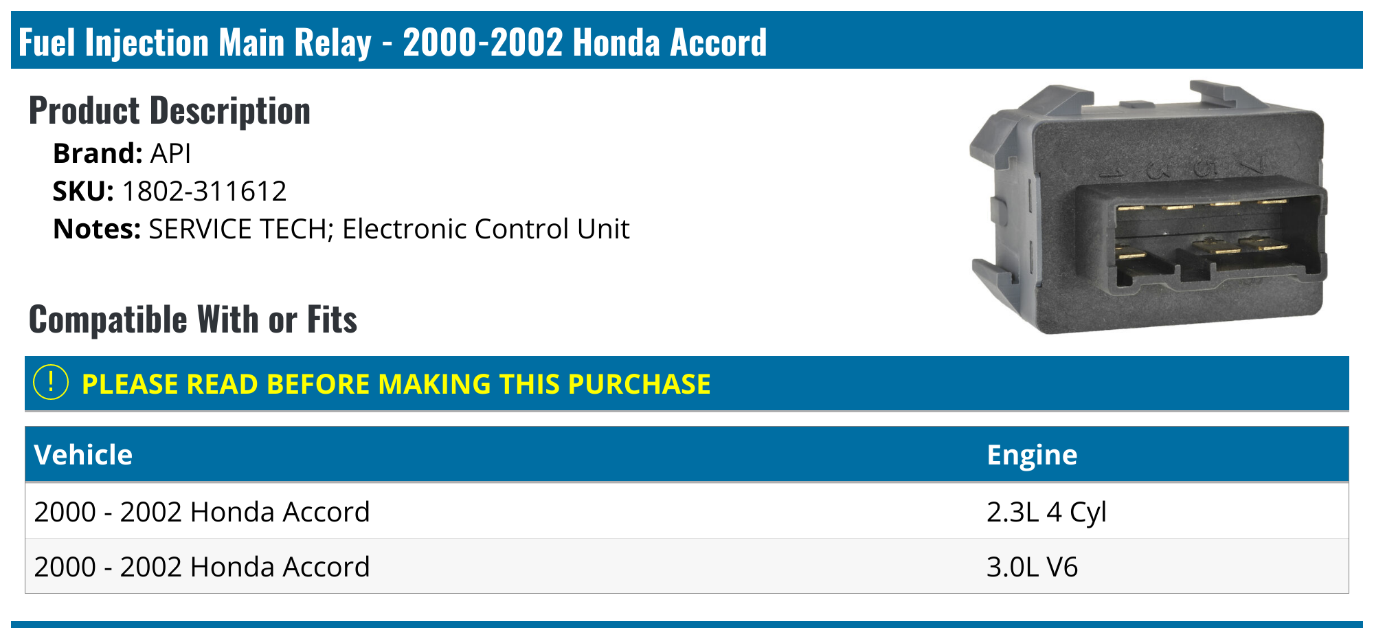
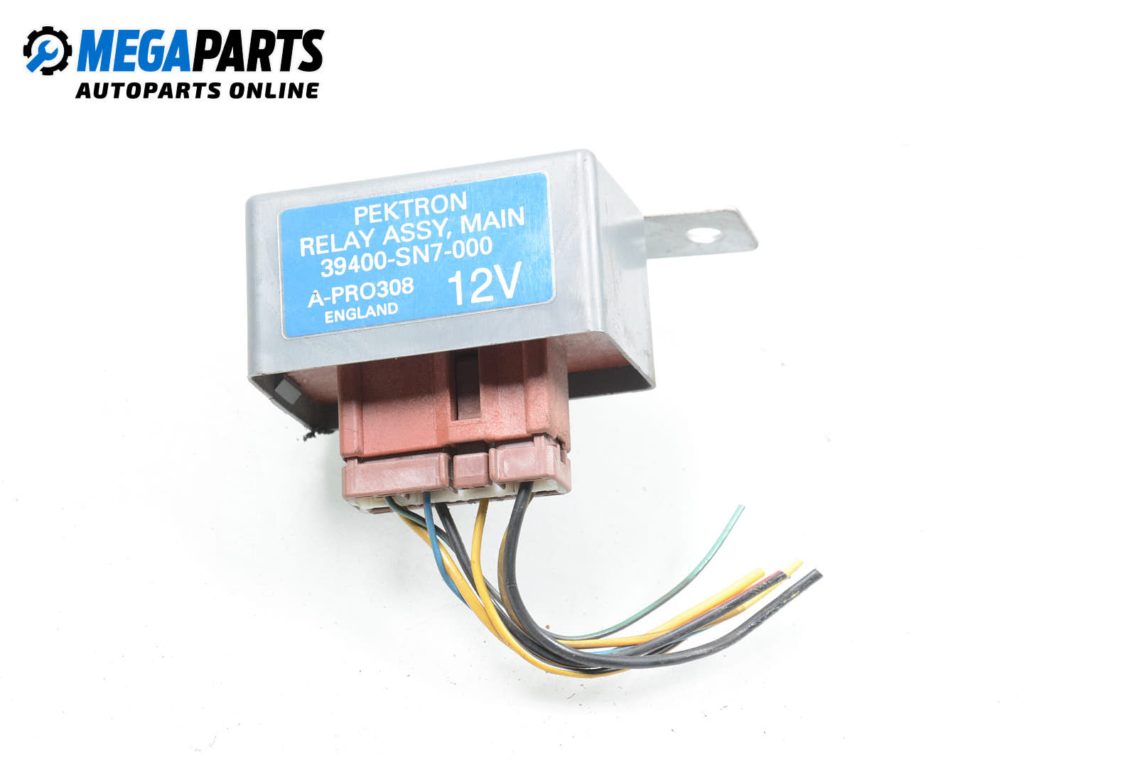
The 2001 Honda Accord fuel pump relay, officially called the PGM-FI main relay, is mounted beneath the driver-side dashboard to the left of the steering column, above the interior fuse panel. It supplies electrical power to both the engine control module and the fuel pump, frequently failing due to cracked internal solder joints when the cabin interior heats up.
Understanding the PGM-FI Main Relay in the 6th-Generation Accord
In the sixth-generation Honda Accord (produced for the 1998 through 2002 model years, spanning both the 2.3L inline-four F23A engines and the 3.0L V6 J30A1 engines), Honda does not utilize an isolated, single-circuit fuel pump relay. Instead, fuel pump operation is controlled through an integrated dual-relay assembly designated as the Programmed Fuel Injection (PGM-FI) main relay.
This single modular component houses two separate electromagnetic relays sharing a small internal printed circuit board (PCB):
- The First Relay (ECU/Sensor Relay): Energizes immediately when the ignition switch turns to the "ON" (II) position. It routes continuous 12-volt battery power to the Engine Control Unit (ECU/ECM), the mass airflow or manifold absolute pressure circuits, the oxygen sensor heaters, and the fuel injectors.
- The Second Relay (Fuel Pump Relay): Works under the direct logic control of the ECU. When the ignition key turns to the "ON" (II) position, the ECU provides a brief ground path to this second coil for approximately two seconds, turning on the electric fuel pump inside the fuel tank to prime the fuel rail. Once the engine starts cranking or running, the distributor or crankshaft position sensor pulses signal the ECU to maintain that ground path, keeping the fuel pump continuously energized.
Because both vital circuits are packaged together within a plastic casing—typically manufactured for Honda by Mitsuba—failure of this component halts either fuel injection, fuel pressurization, or both simultaneously. Understanding this architecture is essential for isolating no-start conditions from dead fuel pumps or faulty ignition switches.
2001 Honda Accord Fuel Pump Relay Location
Finding the PGM-FI main relay on a 2001 Accord requires working within the tight confines of the driver-side footwell. Unlike common automotive relays located in the under-hood power distribution center, Honda positioned this relay inside the passenger cabin.
Exact Physical Position
The relay is positioned high under the far left side of the driver-side dashboard, situated above the interior driver-side kick-panel fuse box and to the left of the steering column assembly. It is secured to a stamped sheet-metal bracket with a single 10mm bolt or slid into a plastic mounting rail attached to the pedal support structure.
The relay itself is an enclosed, rectangular plastic box, usually brown, black, or dark gray, roughly the size of a deck of playing cards. A single 7-pin electrical harness connector plugs into the bottom face of the relay housing.
Accessing the Relay
Direct access from sitting in the driver’s seat is impossible. To access and extract the unit cleanly:
- Move the driver's seat as far back as possible to create working room.
- Remove the lower driver-side knee bolster panel (the plastic trim panel under the steering column) by unscrewing the quarter-turn fastener clips and retaining screws.
- Remove the metal knee bolster reinforcement plate if equipped, using a 10mm socket.
- Position a bright shop light into the pedal box and recline upward on your back beneath the dash.
- Look upward past the emergency brake pedal mechanism and the interior fuse junction block. You will see the wiring bundle leading upward into the rectangular Mitsuba relay casing.
Primary Symptoms of a Failing Main Relay
The failure pattern of the 2001 Honda Accord fuel pump relay is among the most documented diagnostic issues in Honda platforms. Because the underlying problem is typically mechanical fatigue of electrical connections inside the relay rather than an instantly burned-out coil, the symptoms progress in a distinct, predictable pattern.
1. Cranks But Will Not Start on Hot Days (Thermal Soak)
The hallmark sign of a deteriorating PGM-FI main relay is a vehicle that starts reliably in cool morning weather or during cold months, but experiences a complete "crank-no-start" condition after sitting parked in direct sunlight with the windows rolled up.
Solar radiation and residual engine heat soak through the firewall, raising the ambient temperature under the dashboard to over 120°F (49°C). Heat causes the copper relay traces, solder alloy, and brass terminal pins to expand at different rates. Microscopic hairline fractures across the solder pads open up under thermal expansion, breaking circuit continuity to the fuel pump coil. Once the car is ventilated with the doors open or the interior air cools down, the solder contracts, contact resumes, and the vehicle starts normally.
2. Absence of the Two-Second Fuel Pump Priming Hum
Under standard operation, turning the ignition key from "ACCESSORY" (I) to "ON" (II) without turning it all the way to "START" (III) initiates a sequence:
- The dashboard warning lights illuminate.
- The Check Engine Light (CEL) turns on solid.
- A quiet, mechanical hum or buzz can be heard coming from the back seat/fuel tank area for exactly two seconds.
- A soft click sounds under the dashboard, the CEL turns off, and the buzzing ceases.
If the fuel pump relay fails, you will hear the initial dash click, but the steady two-second hum from the rear fuel tank will be absent. The Check Engine Light will often remain illuminated indefinitely without turning off after the two-second prime cycle.
3. Sudden Engine Stalling While Driving
While less common than a no-start condition, severe solder fractures can cause the relay to drop voltage while the vehicle is in motion. Engine vibration or driving over bumps can jar the broken solder joint apart. When this happens, the fuel pump cuts out instantly, or the ECU loses power, causing the engine to shut down immediately without warning, stutter, or sputtering. The engine can typically be cranked right away, but will not catch until the relay contacts reconnect.
4. Intermittent Starting Followed by Immediate Dying
In cases where only the secondary contact or the ECU-feedback circuit drops voltage, the engine may catch for a fraction of a second on residual fuel rail pressure or brief initial prime, only to shut off instantly the moment the ignition key springs back from "START" (III) to "ON" (II).
Detailed Diagnostic Sequence: Testing the Relay
Before purchasing a replacement relay or dropping the fuel tank to swap the fuel pump, execute this logical diagnostic sequence using basic observation and a digital multimeter (DMM).
- Ignition Key to "ON" (II)
- Do you hear Relay Clicks & Fuel Pump Hum (2 sec)?
- YES: Main relay is functioning. Check ignition/spark or mechanical fuel issues.
- NO: Check dash Check Engine Light (CEL) behavior.
- Do you hear Relay Clicks & Fuel Pump Hum (2 sec)?
- Check Engine Light (CEL) Action:
- CEL turns on, then OFF after 2 sec (Relay cycling, but no pump noise):
- Test voltage at fuel pump connector under trunk access panel.
- CEL stays ON indefinitely or never lights up:
- Inspect Fuse #46 (Under-Hood) & Fuse #13 (Driver-side interior). Perform 7-Pin Connector Multimeter Continuity & Voltage Test.
- CEL turns on, then OFF after 2 sec (Relay cycling, but no pump noise):
Phase 1: The Three-Click Auditory Test
Sit in the driver's seat with the vehicle parked in a quiet area. Turn off the radio, climate control fan, and roll up the windows to isolate interior noise. Place your hand under the dash touching the main relay body if reachable, or listen closely near the lower left dash:
- Turn key from OFF to ON (II): You should hear a distinct, crisp Click #1 from the relay. This is Relay 1 closing to power the ECU.
- Immediate Listen: Simultaneously, the Check Engine Light on the gauge cluster illuminates, and you should hear a quiet, smooth whirring hum from the fuel tank behind you.
- Two Seconds Later: You should hear Click #2 from the main relay. Simultaneously, the Check Engine Light turns off, and the fuel pump hum stops.
- Turn key to START (III): As the starter motor engages, you should hear Click #3, which is the fuel pump relay re-engaging to maintain continuous pump power while cranking.
If you hear Click #1, but Click #2 never arrives, the Check Engine Light stays locked on, and no hum is produced in the tank, the fuel pump relay sub-circuit is inoperative.
Phase 2: Upstream Fuse Verification
Do not condemn the relay until verifying that battery voltage reaches the harness. Inspect two distinct fuses:
- Under-Hood Fuse/Relay Box: Check Fuse 46 (15A), which supplies constant, unswitched battery voltage (+B) to the primary relay contacts.
- Driver-Side Under-Dash Fuse Box: Check Fuse 13 (7.5A), which supplies switched ignition voltage (IG1) when the key turns to positions II and III.
If either fuse is blown, the relay will not click or pass voltage. If the fuses are intact, remove the connector from the relay and perform pinout probing.
Phase 3: Main Relay 7-Pin Connector Pinout Voltage Checks
Unplug the 7-wire harness from the main relay. Using a digital multimeter set to DC Volts with the black negative probe clamped to a solid chassis ground (such as the unpainted steel frame around the brake pedal), probe the harness connector terminals:
| Terminal Pin # | Wire Color (Typical 2001 Accord) | Circuit Function | Expected Measurement | Diagnostic Condition |
|---|---|---|---|---|
| Pin 1 | Yellow/Black | Switched 12V Output | 12V (Battery Voltage) | Key in ON (II) or START (III) |
| Pin 2 | Blue/Orange (or Yellow/Blue) | Starter Signal Input | 10V–12V | Only while key is held in START (III) |
| Pin 3 | Black | Ground Path | Continuity to Ground (< 0.5 Ω) | Constant at all times |
| Pin 4 | Yellow/Green | Fuel Pump 12V Output | 12V for 2 seconds, then 0V | Key turned from OFF to ON (II) |
| Pin 5 | Black/Red | ECU Relay Ground Control | Logic Ground (< 1.0V) | Pulses low when commanded by ECU |
| Pin 6 | Blue/White | Ignition Switch (IG1) Input | 12V (Battery Voltage) | Key in ON (II) or START (III) |
| Pin 7 | White/Green | Battery (+B) Constant Power | 12V (Battery Voltage) | Constant at all times (Key OFF or ON) |
Note: Wire colors can occasionally vary between early and late production dates or between 4-cylinder (F23A1/A4/A5) and V6 (J30A1) engine trims. Always confirm pin layout geometry relative to the connector locking tab before testing.
Interpreting Harness Voltage Findings:
- If Pin 7 lacks 12V: The problem lies in the wiring harness or under-hood Fuse 46.
- If Pin 6 lacks 12V with the key in ON (II): The electrical ignition switch assembly (mounted on the back of the key cylinder, another common failure item on 1998–2002 Accords) is open or worn out.
- If Pin 3 has high resistance to ground (> 1.0 Ω): Clean and re-torque the chassis ground point (G101 on the intake manifold/chassis ground lugs).
- If all pin inputs (Pins 2, 3, 6, 7) test correctly, but Pin 4 fails to output 12V for two seconds when the relay is plugged in: The main relay is defective.
Bench Testing the PGM-FI Relay
If you have extracted the relay from under the dashboard and wish to confirm failure before replacing or repairing it, bench testing requires only a 12V power supply (or a healthy car battery), test leads with alligator clips, and a digital multimeter set to resistance (Ohms).
- 12V Battery Positive (+)
- Pin 6 (Relay Coil 1)
- Pin 3
- 12V Battery Negative (-)
- Pin 3
- Pin 7 (Relay 2 Contact)
- Pin 4
- Multimeter (+)
- Multimeter (-)
- 12V Battery Negative (-)
- Multimeter (-)
- Multimeter (+)
- Pin 4
- Pin 6 (Relay Coil 1)
- (Also connect Pin 5 to Negative to activate Relay 2)
Test Relay 1 (ECU Main Power Circuit):
- Connect 12V positive to Pin 6.
- Connect 12V negative/ground to Pin 3.
- The relay should produce an audible click.
- With voltage applied, check for continuity (0.0 to 0.2 Ω) between Pin 1 and Pin 7.
- Remove power; continuity must immediately break (infinite/OL).
Test Relay 2 (Fuel Pump Circuit):
- Keep 12V positive connected to Pin 6 and negative to Pin 3.
- Apply 12V positive to Pin 7.
- Connect 12V negative to Pin 5 (simulating the ECU grounding the fuel pump circuit).
- A second click must sound.
- Check for continuity (0.0 to 0.2 Ω) between Pin 7 and Pin 4.
- Disconnect Pin 5 from ground; the continuity between Pin 7 and Pin 4 must break.
If either internal relay fails to click, or if the click sounds but the multimeter displays high resistance or an open circuit (OL) across the respective output pins, the internal contacts are pitted, or the internal solder joint connections are fractured.
Root Cause Analysis: The Thermal Solder Joint Defect
Automotive enthusiasts and technicians often ask why Honda main relays from this era fail with such regularity. The cause is metallurgical fatigue combined with cabin packaging design.
Relay PCB Board Cross-Section:
- Terminal Pin (Stiff Brass)
- Printed Circuit Board (FR-4)
- Solder Ring Fracture (Thermal expansion causes micro-cracking around pin base)
- Copper Circuit Trace
Inside the plastic casing, the electromagnetic coils and external harness terminals are joined together on a small printed circuit board using a wave-soldering process. During the late 1990s and early 2000s, automated soldering standards and thermal stress tolerances for under-dash electronics were less robust than modern standards.
- Differential Thermal Expansion: The heavy brass terminal pins expand and contract at a significantly different rate than the fiberglass circuit board and the lead-tin solder surrounding them.
- Vibrational Strain: Because the main relay hangs directly above the driver’s footwell without vibration dampeners, road vibration constantly flexes the heavy copper coils against the solder joints.
- Ring Fractures: Over thousands of heating and cooling cycles, microscopic ring cracks form around the base of the terminal pins—especially the ground pin and the main power supply pins.
- Oxidation: Once the crack forms, electrical arcing across the gap oxidizes the exposed lead and tin surfaces, turning them dull gray and non-conductive. When the cabin warms up, the metal ring expands away from the pin, terminating all power delivery to the fuel pump.
How to Repair vs. Replace the Relay
When facing a failed 2001 Accord main relay, you have two practical remedies: replace the assembly with a new unit or reflow the internal solder joints.
Option A: Reflowing the Solder Joints (DIY Zero-Cost Repair)
Because the mechanical coils, return springs, and copper contacts rarely burn out, resoldering the factory board permanently fixes the issue if done correctly.
Tools Required
- 30W to 60W fine-tip soldering iron.
- 60/40 Rosin-core solder (or high-grade 63/37 leaded electronics solder; avoid lead-free solder for repairs as it requires higher heat and is more brittle).
- Desoldering pump or copper desoldering braid.
- Rosin flux paste or liquid flux pen.
- Isopropyl alcohol (90%+ purity) and a soft brush.
- Small flathead screwdriver.
Step-by-Step Reflow Procedure
- Open the Casing: Insert a thin flathead screwdriver between the brown/black plastic cover and the lower connector base. Gently pry outward on the locking tabs on both sides and slide the internal board assembly out of its protective case.
- Inspect the Solder Pads: Examine the solder side of the board under strong lighting with a magnifying glass or jeweler’s loupe. Look closely at the larger terminal solder joints. You will see subtle, dark circular rings or hairline cracks running around the perimeter of the pins.
- Clean the Old Flux: Clean off any factory protective varnish or residue using isopropyl alcohol and a brush.
- Remove Old, Oxidized Solder: Apply a touch of fresh flux, place the hot soldering iron tip onto the cracked joint until it melts fully, and extract the oxidized solder with a desoldering pump.
- Apply Fresh Solder: Touch the iron tip simultaneously to the copper circuit board pad and the brass pin for 2 to 3 seconds to heat both evenly. Feed fresh rosin-core solder into the joint until it forms a smooth, shiny, concave fillet (like a small volcano). Do not create a rounded, bulbous ball of solder or allow solder to bridge adjacent traces.
- Repeat on All Major Joints: Reflow not just the cracked joints, but all 7 harness pin connections and the relay coil connections. Addressing every pin prevents a different joint from failing a year down the road.
- Clean and Reassemble: Clean away residual flux using isopropyl alcohol, allow the board to dry completely, inspect for accidental solder bridges, and slide the board back into its plastic shell until the retainers click.
Option B: Replacing with a New Unit
If you prefer installing a new component, replacement assemblies are readily available:
- OEM Honda Part: Original equipment units (historically distributed under Honda part numbers such as 39400-S84-003 or RZ-0159) offer factory reliability.
- Aftermarket Units: Brands like Standard Motor Products (RY-422), Wells/Duralast (19302), and Beck/Arnley manufacture direct replacements.
- Buyer Warning: Avoid unbranded, ultra-cheap offshore clone relays sold on discount marketplaces. Many use undersized relay coils and inferior plastic casings that can warp under typical interior dashboard heat, failing within weeks of installation.
Step-by-Step Replacement Instructions
Replacing the relay is straightforward mechanically, though it requires working in an awkward physical posture.
- Preparation: Disconnect Battery (-) Terminal
- Disassembly: Drop Driver-Side Lower Dashboard Cover
- Access: Unbolt 10mm Mounting Bracket or Slide Relay from Clip
- Extraction: Depress Harness Locking Tab & Disconnect Connector
- Installation: Plug Harness into New Relay (Audible "Click")
- Verification: Reconnect Battery & Perform 2-Second Prime Test
- Reassembly: Secure Bracket, Remount Dash Trim Panels
Necessary Tools
- 1/4-inch drive ratchet.
- 10mm shallow and deep sockets.
- 6-inch extension bar.
- Phillips head screwdriver.
- Trim panel removal tool (or flathead screwdriver wrapped in tape).
- Drop light, headlamp, or magnetic inspection light.
Removal Procedure
- Safety First: Set the emergency parking brake. Disconnect the negative terminal of the 12V battery under the hood to eliminate the possibility of accidental electrical shorts while working near the under-dash fuse block.
- Drop Lower Dash Trim:
- Turn the plastic quarter-turn fasteners on the lower knee bolster to the left.
- Remove the single Phillips screw located at the bottom-right or lower-left corner of the bolster.
- Carefully pull the bolster straight outward to release the metal retention snaps along the top edge.
- Set the plastic panel aside.
- Locate the Relay: Don your headlamp, lie on the floorboard with your head beneath the pedal box, and look upward past the clutch pedal (manual) or wide brake arm (automatic). Locate the rectangular relay mounted to the left of the steering column.
- Unhook the Assembly:
- Method A (Easiest): Often, the relay housing is attached to its bracket via a plastic slide track. Grasp the relay body firmly, depress the release tongue, and slide the relay straight upward or sideways off its metal bracket, leaving the bracket bolted to the car.
- Method B: If the relay cannot be slid off its bracket, use your 1/4-inch ratchet with a 10mm socket and 6-inch extension to remove the single 10mm bolt securing the metal bracket to the upper firewall framework.
- Disconnect the Harness: With the relay freed from its mounting point and lowered slightly into view, depress the center locking clip on the 7-pin electrical connector firmly. Pull the connector housing away from the relay body. Do not tug directly on the wires.
Installation and Verification
- Connect the New Relay: Line up the 7-pin harness connector with the socket on the new relay. Push firmly until you hear and feel the plastic retention tab snap securely into place.
- Temporary Pre-Assembly Test:
- Before bolting the dash back together, reconnect the negative battery terminal under the hood.
- Insert the ignition key into the ignition cylinder.
- Turn the key to "ON" (II).
- Confirm that the relay clicks, the fuel pump runs for two seconds with a clear hum from the rear, and the Check Engine Light turns off after two seconds.
- Turn the key to "START" (III) to confirm the engine starts instantly and idles smoothly.
- Secure the Relay: Reattach the relay to its metal bracket or slide it back onto the bracket tang until locked. Ensure the wiring bundle is not pinched against sharp structural metal or resting on the moving linkages of the steering shaft or pedal arms.
- Reassemble the Dashboard: Reinstall the metal knee bolster plate (if removed) with its 10mm bolts, align the lower dashboard cover, snap the retaining clips into place, and turn the quarter-turn fasteners to lock the trim.
Comparison of Similar Starting and Stalling Issues
A no-start condition on a 2001 Accord is not exclusively caused by the main relay. Because components like the ignition switch, the fuel pump itself, and the ignition distributor can produce overlapping symptoms, use this comparative guide to confirm your diagnosis:
| Component | Failure Pattern | Key Distinguishing Symptom | Relay Click Sound Present? | Dash Warning Lights Status |
|---|---|---|---|---|
| PGM-FI Main Relay | Intermittent; worst when interior cabin is hot; starts fine cold. | Engine cranks vigorously; fuel pump makes no priming sound for 2 seconds. | Click 1 occurs; Click 2 usually fails. | Check Engine Light stays illuminated indefinitely during key ON. |
| Ignition Switch (Electrical Portion) | Sudden stalling when hitting bumps; car dies the moment key returns to "II". | Jiggling the key in the ignition cylinder cuts the engine or causes dash lights to flicker. | Yes, clicks intermittently as key position shifts. | Instrument cluster lights completely black out when stalling occurs. |
| Fuel Pump Motor | Gradual degradation or permanent sudden death; temperature independent. | 12V is confirmed present at fuel pump connector under trunk floor, but pump does not spin. | Yes; full 3-click cycle operates under the dash normally. | Check Engine Light cycles on and off normally after 2 seconds. |
| Ignition Distributor (Igniter/Coil) | Cranks but will not start, or shuts down violently after reaching operating temp. | Fuel pump primes normally; fuel injectors pulse; zero spark output at spark plug wires. | Yes; clicks completely normally. | Normal dash warning light cycling; tachometer may drop instantly to zero. |
| Immobilizer System (T-Type) | Engine starts, runs for exactly 1.5 seconds, then shuts off cleanly. | Flashing green key indicator light on the instrument cluster gauge faces. | Yes; relay primes correctly on initial key-turn. | Green "Key" light flashes continuously on the instrument cluster. |
Preventative Practices and Expert Maintenance Guidance
If you are maintaining a 2001 Honda Accord, several actionable practices will prevent or mitigate fuel pump relay failures:
Avoid Interior Heat Trapping
Because solder fracture expansion is driven by cabin temperature spikes, crack your vehicle’s windows slightly or use a reflective front windshield sunshade when parking outdoors in peak summer weather. Keeping ambient interior cabin temperatures below 100°F (38°C) drastically reduces the rate of thermal fatigue across all under-dash electronics.
Carry a Known-Good Spare Relay
Given that a failed main relay leaves the vehicle completely stranded without warning, keeping a tested spare relay and a 10mm socket or cross-head screwdriver inside your glove compartment is practical insurance. Swapping the relay requires no specialized mechanical training and can be accomplished on the roadside in under ten minutes.
The Emergency "Bypass/Tap" Workaround
If you are stranded in a parking lot on a hot day with a 2001 Accord that cranks but will not start:
- Open all four car doors and allow the interior to vent for five to ten minutes.
- Turn the air conditioning blower vents downward toward the pedals once moving, or allow the floorboard area to cool down.
- Locate the relay under the left dash with your hand, or tap firmly on the lower-left knee bolster plastic with the heel of your hand or a screwdriver handle while turning the key to "ON" (II).
- The physical shock from tapping often jolts the separated solder contacts together long enough to trigger the fuel pump prime and start the vehicle, allowing you to drive home safely before performing a permanent repair.
Frequently Asked Questions
What fuse controls the fuel pump relay on a 2001 Honda Accord?
Two fuses protect the PGM-FI main relay circuit on a 2001 Accord. Under the hood in the primary engine bay fuse box, Fuse 46 (15A) supplies constant unswitched battery power to the relay contacts. Inside the cabin in the driver-side lower kick panel fuse box, Fuse 13 (7.5A) delivers switched power to the relay control coils whenever the ignition switch is turned to the ON (II) or START (III) positions. Both must be intact for the relay to function.
Can a bad fuel pump relay cause an Accord to stall while driving?
Yes. While the most common symptom is failing to start when the car is hot, vibration or severe temperature fluctuations can cause the micro-cracks on the relay's internal circuit board to separate while the engine is running. If continuity across the fuel pump circuit or the ECU power circuit breaks while driving, the fuel pump cuts off or the fuel injectors cease firing instantly, causing the engine to shut down immediately without preliminary sputtering.
How do I know if the problem is my main relay or the fuel pump itself?
The most reliable test is listening for the prime hum while monitoring the Check Engine Light (CEL), followed by checking voltage at the fuel pump access panel located inside the trunk. If the main relay is defective, the CEL will typically stay illuminated during the prime cycle, no click will sound under the dash to turn the pump off after two seconds, and zero volts will reach the fuel pump connector in the trunk. If the relay is good, you will hear the relay click off after two seconds, you will measure 12V at the fuel pump connector during those two seconds, but the pump motor will make no noise and build no pressure.
Where is the fuel pump access panel located on the 2001 Accord?
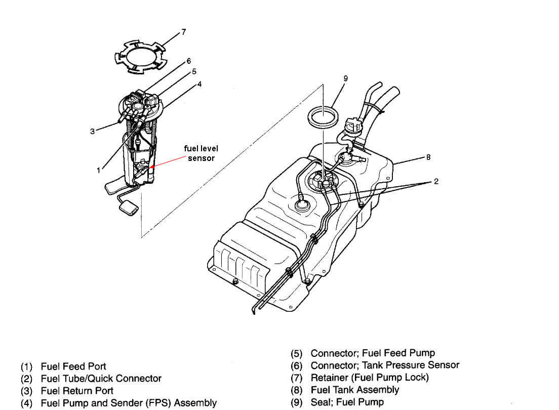
The fuel pump assembly on the 1998–2002 Honda Accord is accessed through the trunk, not from underneath the rear seat. Pull back the trunk carpeting directly behind the rear seatback to reveal an oval or rectangular metal inspection plate secured by three Phillips head screws. Removing this plate exposes the fuel pump module's top wiring harness, allowing direct electrical multimeter testing of the yellow/green power wire without dropping the fuel tank.
Why does my 2001 Accord start fine when cold, but won't start after sitting in the sun?
This condition, known as thermal soak failure, is caused by thermal expansion within the main relay. The relay board uses brass pins soldered into a fiberglass circuit board. As interior cabin temperatures rise on sunny days, the differing expansion rates of the brass, solder, and circuit traces force microscopic cracks around the solder joints to spread apart, severing the connection. Once the cabin cools, the metals contract, reconnecting the circuit and allowing the fuel pump to prime normally again.
Next Steps and Recommended Actions
If your 2001 Honda Accord exhibits hot-start issues or sudden cutouts, begin by performing the Three-Click Auditory Test in your driveway. Listen closely for the secondary relay click and the corresponding fuel pump prime hum beneath the rear trunk floor. If the fuel pump fails to prime and your under-dash fuses (Fuse 13 and Fuse 46) are intact, remove the lower driver's side knee bolster to access the PGM-FI relay.
Inspect the internal circuit board for dull, circular cracks around the solder pins under magnification. You can resolve the failure permanently by applying fresh leaded rosin-core solder to each terminal joint with a standard soldering iron, or by installing a verified OEM-grade replacement relay assembly (Part #39400-S84-003 or equivalent). Ensuring this circuit is restored guarantees reliable starting across all weather conditions and eliminates one of the most frequent roadside failure modes on the 6th-generation Honda Accord.