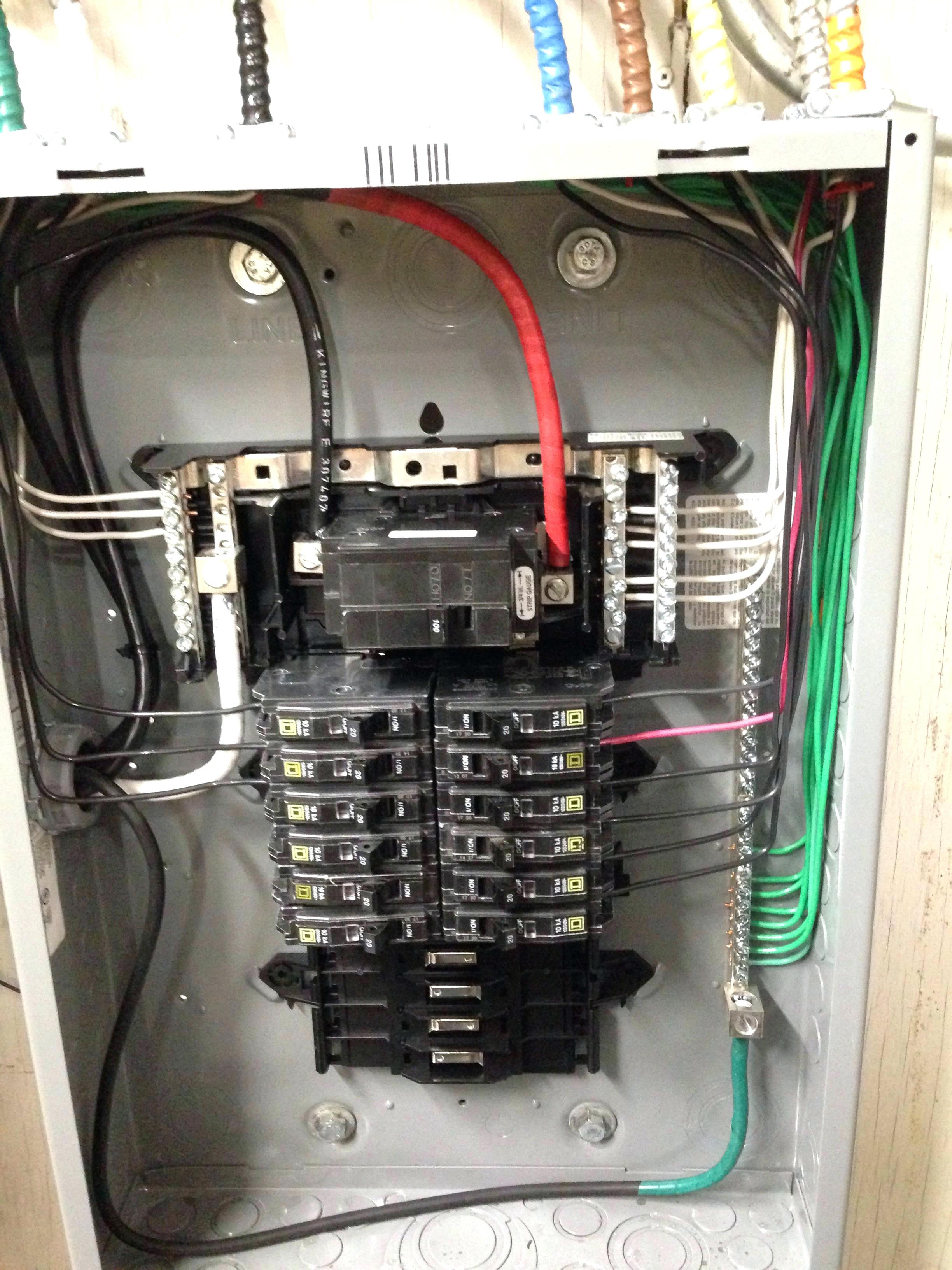
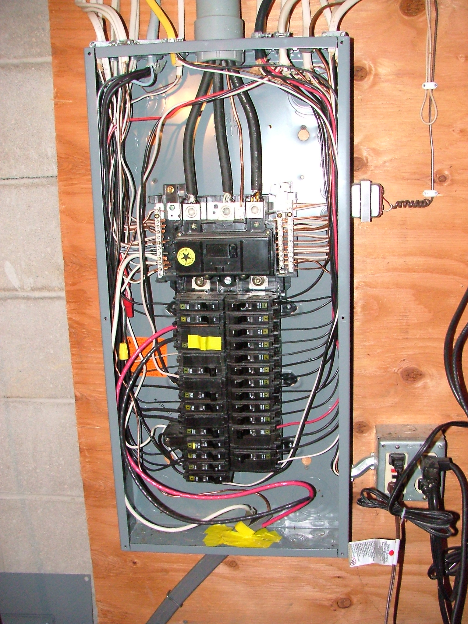
A 100-amp breaker box serves as a primary electrical distribution panel for a home or outbuilding, routing electricity from the utility service safely through individual circuits while protecting against overloads and short circuits. Proper wiring requires a firm understanding of service entrance cables, hot and neutral bus bars, grounding and bonding systems, and compliance with the National Electrical Code (NEC).
Understanding the Anatomy of a 100-Amp Electrical Panel
Before examining the installation and wiring procedures, it is necessary to examine the physical architecture of a 100-amp breaker box. The panel is a metal enclosure that houses several key electrical components designed to manage heavy electrical loads safely.
At its core, a breaker box receives power from an external meter socket via large service entrance conductors. These conductors connect directly to the main breaker—a heavy-duty switch rated at 100 amps—which can shut off power to the entire panel simultaneously. From the main breaker, electricity flows to two hot bus bars that run vertically or horizontally through the center of the box. Individual single-pole and double-pole circuit breakers snap onto these bus bars, distributing power to specific rooms, appliances, and dedicated outlets throughout the property.
- MAIN 100-AMP BREAKER
- Hot Bus A (120V Phase 1) and Hot Bus B (120V Phase 2)
- Breaker 1 (15A) and Breaker 2 (20A)
- Breaker 3 (30A Double) and Breaker 4 (15A)
- Neutral Bus Bar (receives White Neutral Wires)
- Ground Bus Bar (receives Bare/Green Ground Wires)
In addition to the hot bus bars, a modern panel features dedicated neutral and ground bus bars. The neutral bus collects return current from 120-volt circuits, while the grounding bus collects bare copper or green insulated equipment grounding conductors. Depending on whether the panel acts as a "main service panel" or a "subpanel," these neutral and ground bars may be bonded together or kept strictly separated.
Technical Specifications and Wire Sizing for 100 Amps
Selecting the correct wire size is critical when working with a 100-amp electrical service. Undersized wire will resist electrical flow, generating dangerous levels of heat that can melt insulation and cause electrical fires. Wire gauge is measured using the American Wire Gauge (AWG) system, where smaller numbers denote thicker conductors.
The size of the wire required depends on the material (copper versus aluminum) and the ampacity rating of the insulation. For a 100-amp main service feed, standard industry practices dictate specific minimum wire sizes:
- Copper Wire: Requires a minimum of 2 AWG copper conductor for standard 75°C or 90°C rated insulation (such as THHN/THWN-2 or SER cable).
- Aluminum Wire: Requires a minimum of 1 AWG (or frequently 1/0 AWG) aluminum conductor because aluminum has lower electrical conductivity than copper and requires a larger cross-sectional area to carry the same current safely.
Branch Circuit Wire Sizing
While the main service feed requires heavy-gauge wire, individual branch circuits originating from the 100-amp box require wire sizes tailored to their specific breaker ratings:
- 15-Amp Breakers: Require 14 AWG copper wire (used for general lighting and standard bedroom/living room outlets).
- 20-Amp Breakers: Require 12 AWG copper wire (used for kitchens, bathrooms, laundry rooms, and dedicated appliance outlets).
- 30-Amp Breakers (240V): Require 10 AWG copper wire (used for electric water heaters, dryers, or small RV hookups).
- 50-Amp Breakers (240V): Require 6 AWG copper wire (used for electric ranges or large subpanels).
Step-by-Step Wiring and Installation Overview
Working inside a live electrical panel exposes an individual to lethal voltages. Professional electricians utilize specialized safety gear, insulated tools, and local utility coordination to disconnect power before opening the dead front cover.
1. Planning and Load Calculation
Before mounting a 100-amp breaker box, perform a standard NEC load calculation to ensure the 100-amp service is sufficient for the total connected electrical load. While 100 amps is adequate for small homes, apartments, workshops, or detached garages, modern single-family dwellings often require 200-amp service to handle central air conditioning, electric vehicle chargers, and modern kitchen appliances.
2. Mounting the Enclosure
Secure the metal breaker box directly to wall studs or masonry using appropriate structural fasteners. The center of the operating handle of the highest breaker must not be positioned more than 6 feet, 7 inches above the floor, in compliance with NEC accessibility guidelines. Ensure the knockout holes used for cable entry match the connector sizes.
3. Running Service Entrance Cables and Conduit
Feed the main service cable (such as 2-2-2-4 aluminum SER cable or individual conductors pulled through rigid metal or PVC conduit) into the top or bottom of the panel through listed cable clamps or conduit fittings. Secure the cable to the framing members within 12 inches of the panel enclosure.
4. Connecting Hot, Neutral, and Ground Conductors
- Hot Wires: Connect the two ungrounded hot service conductors directly to the lugs of the main 100-amp breaker. Torque the terminal screws to the manufacturer's precise specification (measured in inch-pounds) using a calibrated torque wrench.
- Neutral Wire: Strip the white neutral conductor and secure it firmly to the neutral terminal bar. Apply an antioxidant paste if using aluminum conductors.
- Grounding and Bonding: Connect the bare copper grounding electrode conductor from your ground rods and water pipe bond to the grounding bus bar.
5. Installing Branch Circuit Breakers
Snap individual circuit breakers onto the hot bus bars. Insert the hot wire (black or red) into the terminal screw of the breaker and tighten it securely. Route the white neutral wire of that specific circuit to the neutral bus bar, and connect the bare copper ground wire to the grounding bus bar.
Main Panel vs. Subpanel Wiring Rules
A common point of confusion during installation is distinguishing between a main service panel and a subpanel. The wiring rules differ significantly based on the panel's location relative to the utility meter.
| Feature | Main Service Panel | Subpanel (Detached or Remote) |
|---|---|---|
| Location | First point of disconnect (near meter). | Located downstream from the main panel. |
| Main Breaker | Required to shut off all power. | May or may not require a main breaker (depends on location). |
| Neutral-Ground Bond | Bonded: Neutral and ground bars are connected together with a green bonding screw or strap. | Isolated: Neutral and ground bars must be completely separated; an independent grounding electrode system is required. |
| Conductors | Hot, Neutral, Ground, and Service Grounding. | Four wires required: Two Hots, One Neutral, One Separate Ground. |
When wiring a 100-amp subpanel in a detached garage or workshop, you must run four separate wires from the main panel: two hot wires, one insulated neutral wire, and one dedicated equipment grounding wire. The neutral bar in the subpanel must float (isolated from the enclosure), and the subpanel must be bonded to its own earth grounding system consisting of two ground rods driven at least 6 feet apart.
Safety Measures, Code Compliance, and Common Mistakes
Electrical installations are strictly governed by the National Electrical Code (NEC) and local building regulations. Failing to adhere to these standards can result in failed inspections, equipment damage, or fatal shocks.
Critical Safety Rules
- Always Call the Utility Company: Never attempt to pull an electric meter or tamper with service drop lines. Only authorized utility personnel can disconnect power at the transformer or meter base.
- Use a Voltage Tester: Always verify that power is completely off using a reliable, calibrated digital multimeter or non-contact voltage tester before touching any internal bus bar.
- Torque Specifications: Loose terminal connections create high-resistance points that generate localized heat, leading to arcing faults and electrical fires. Always use a torque screwdriver.
Common Wiring Mistakes to Avoid
- Double-Tapping Breakers: Unless a circuit breaker is explicitly rated and labeled by the manufacturer to accept two conductors, inserting two wires under a single breaker terminal violates the NEC and creates a loose connection.
- Mixing Neutral and Ground in Subpanels: Connecting the neutral wire to the ground bus bar in a subpanel creates parallel paths for return current, electrifying metal conduit and appliance chassis.
- Failing to Label Circuits: Every single breaker must be legibly and accurately indexed on the panel directory door. Vague descriptions like "Downstairs" or "Plugs" do not meet code requirements.
Disclaimer: Electrical work carries inherent risks of electrocution, severe injury, and structural fires. This guide is for educational purposes and does not replace professional electrical engineering or licensed contracting services. Always consult your local municipality and hire a licensed electrician to pull permits and perform or inspect installation work.
Frequently Asked Questions
What size wire do I need for a 100-amp breaker box?
A 100-amp electrical service feed typically requires a minimum of 2 AWG copper wire or 1/0 AWG aluminum wire. For individual branch circuits inside the panel, wire size varies from 14 AWG for 15-amp circuits up to 6 AWG for 50-amp heavy-duty 240-volt circuits.
Can I install a 100-amp subpanel off a 200-amp main panel?
Yes, you can feed a 100-amp subpanel from a 200-amp main service panel, provided that a properly sized breaker (100 amps or smaller) is installed in the main panel to protect the feeder cable. The subpanel must be wired using four conductors and have isolated neutral and ground buses.
Do I need a main breaker in a 100-amp subpanel?
If the 100-amp subpanel is located inside the same building as the main service panel, a main breaker in the subpanel is technically optional under certain NEC guidelines, though frequently installed for convenience. If the subpanel is located in a separate structure (such as a detached garage or shed), a main disconnect breaker is strictly required.
What is the difference between neutral and ground wires in a breaker box?
Neutral wires carry normal return operating current back to the power source on 120-volt circuits. Ground wires do not carry current during normal operation; instead, they provide a safe, low-resistance path to earth for fault current, tripping the breaker during a short circuit.
How do I properly bond a 100-amp main panel?
In a main service panel, the neutral bus bar must be physically bonded to the metal enclosure and the grounding system using a green bonding screw or stainless steel bonding strap. This ties the neutral return path directly to the grounding electrode conductor connected to ground rods and metal water pipes.