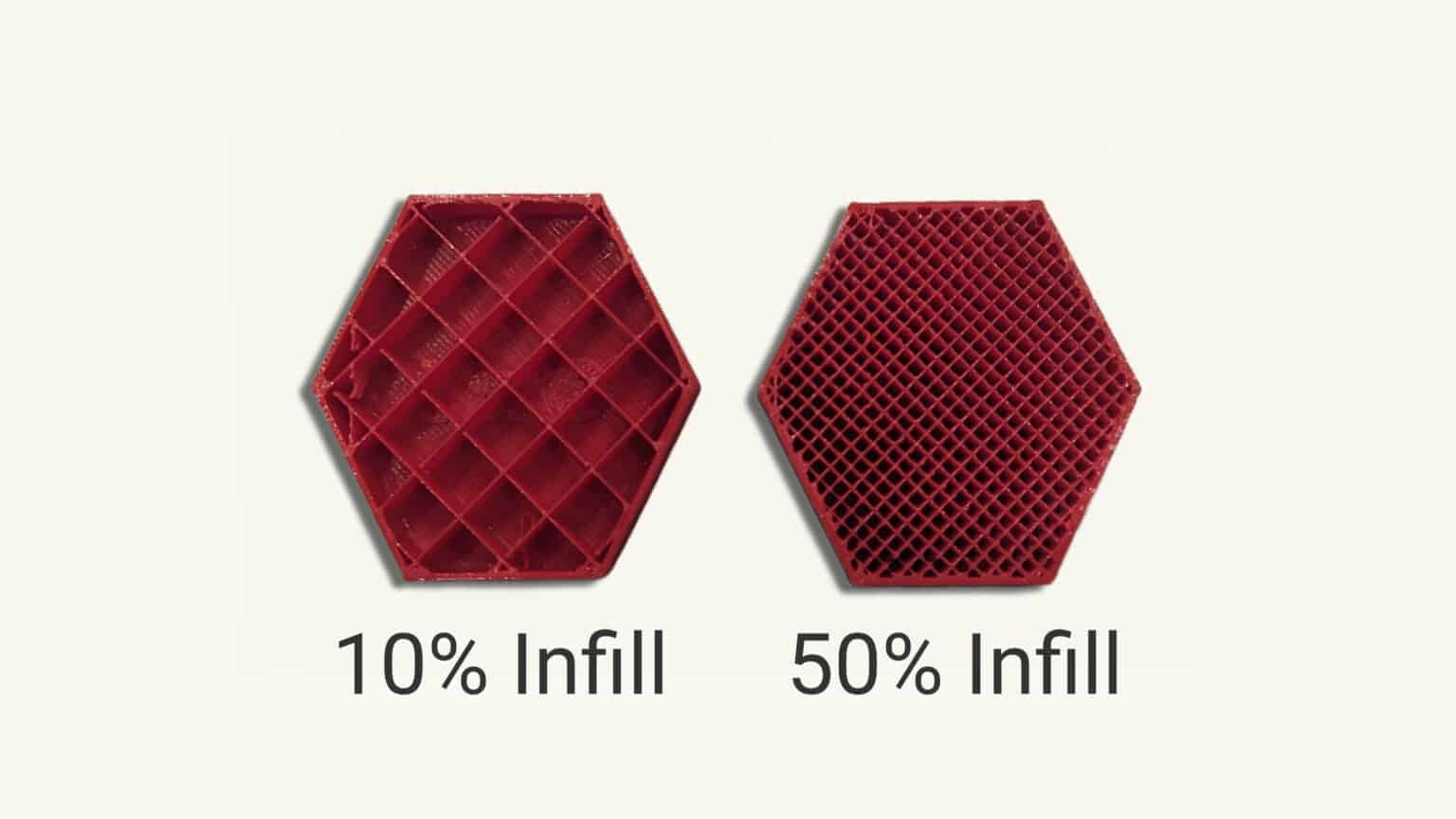
Infill in 3D printing refers to the internal structure of a printed object, acting as a hidden support network between the outer walls. It determines a part’s weight, strength, and print time by filling the hollow interior with various geometric patterns at specific densities rather than solid plastic.
Understanding infill is the bridge between a successful visual prototype and a high-performance functional part. In the world of additive manufacturing, "infill" is a multi-dimensional setting within slicing software that dictates how the internal volume of a 3D model is occupied. While the exterior "shells" or "perimeters" provide the shape and finish, the infill provides the structural integrity and internal support for top-facing surfaces.
As we navigate the manufacturing landscape of 2026, where high-speed printing and advanced composites are standard, optimizing infill has moved from a simple percentage choice to a sophisticated engineering decision. To master this aspect of 3D printing, one must look beyond the surface.
1. The Functional Role of Infill Beyond Structural Support
Most beginners view infill simply as a way to save filament, but its primary engineering role is twofold: providing internal rigidity and acting as a foundation for "top layers." Without infill, a 3D printer would attempt to extrude plastic into mid-air when closing the top of a model, leading to "pillowing" (dips and holes in the top surface) or total print failure.
Internal Rigidity and Impact Resistance
The infill pattern creates a series of internal walls that resist compression and shear forces. Depending on the geometry, some infills are better at resisting forces from specific directions. For instance, a part designed for a shelving bracket requires an infill that resists bending, whereas a protective case for a drone requires an infill that can absorb and dissipate kinetic energy from impacts.
Preventing Thermal Warp
In 2026, with the widespread use of high-temperature engineering filaments like PEEK and carbon-fiber-reinforced polycarbonates, infill plays a crucial role in thermal management. Large, solid blocks of plastic tend to warp as they cool due to internal stresses. A well-designed infill pattern breaks up these stress lines, allowing the part to cool more uniformly and reducing the risk of the corners lifting from the build plate.
2. Deciphering Infill Density: The Law of Diminishing Returns
Infill density is measured as a percentage, where 0% is completely hollow and 100% is a solid block. A common mistake in the 3D printing community is the belief that higher density always equals a better part. In reality, the relationship between density and strength is non-linear.
The 15% to 50% Sweet Spot
For the vast majority of functional parts, an infill density between 15% and 40% provides the optimal balance. Beyond 50%, the increase in mechanical strength begins to plateau, while the consumption of material and print time continues to rise sharply.
- 0-10%: Ideal for visual models, figurines, and non-functional prototypes where weight is the primary concern.
- 15-30%: The standard range for most household items, toys, and light-duty tools.
- 40-70%: Necessary for heavy-duty components, jigs, and fixtures subjected to moderate mechanical stress.
- 80-100%: Reserved for parts requiring maximum weight or specific underwater applications where buoyancy must be minimized.
Strength is in the Walls
Engineering tests consistently show that adding an extra "perimeter" (or wall loop) often increases the overall strength of a part more effectively than increasing the infill density by 20%. This is because the outer shells bear the brunt of the tension when a part is bent. As of 2026, professional slicers now prioritize "wall-heavy" strategies for structural components to maximize efficiency.
3. Geometric Patterns and Isotropic Strength
The pattern of the infill determines how the material is distributed within the volume. Slicing engines now offer dozens of patterns, but they generally fall into three categories based on their geometric properties.
2D vs. 3D Patterns
2D patterns, such as Grid or Triangles, repeat the same shape layer after layer. While they are fast to print, they are "anisotropic," meaning they are much stronger in the vertical (Z) direction than they are in the horizontal (XY) directions.
3D patterns, most notably the Gyroid, create complex, waving structures that change with every layer. These are "isotropic," providing nearly equal strength in all directions. The Gyroid has become the gold standard in 2026 for functional parts because it resists twisting and shearing forces better than any 2D pattern, and it allows for easier drainage of trapped air or resins.
Speed vs. Stability
- Rectilinear/Grid: The fastest to print. Excellent for general-purpose use but prone to "nozzle dragging" where the nozzle crosses over previously printed lines on the same layer.
- Honeycomb: Extremely strong and aesthetically pleasing if the part is translucent, but it takes significantly longer to print due to the frequent direction changes for the print head.
- Cubic: A 3D pattern that provides great strength-to-weight ratios and reduces the likelihood of internal warping.
| Infill Pattern | Strength Direction | Print Speed | Best Use Case |
|---|---|---|---|
| Grid | Vertical (Z) | Very Fast | General prototypes, low-cost parts |
| Gyroid | All Directions (Isotropic) | Medium | Functional mechanical parts, vibration dampening |
| Honeycomb | Lateral (XY) | Slow | Structural rigid components, decorative transparency |
| Cubic | 3D / Torsional | Fast-Medium | Parts requiring high stiffness in multiple axes |
| Lightning | Internal Support Only | Extremely Fast | Large visual models with little internal stress |
4. Advanced Optimization: Gradient and Adaptive Infill
The evolution of slicing algorithms has introduced "Adaptive Infill," which changes the density of the internal structure based on the model's geometry. This is perhaps the most significant insight for modern 3D printing efficiency.
Gradual/Adaptive Infill
Instead of a uniform 20% density throughout the entire part, adaptive infill makes the center of the part hollow (perhaps 5% density) and gradually increases the density as it gets closer to the top surfaces or the outer walls. This ensures that the areas needing support (under the top "roof") are dense enough to prevent sagging, while the bulk of the part remains lightweight and fast to print.
Modifier Meshes
Advanced users utilize "modifier meshes" to manually define areas of high density. If you are printing a lever, you might use 15% infill for the handle but apply a modifier to use 80% infill around the pivot hole where the most stress will occur. This localized reinforcement mimics natural structures, like bones, which are denser at points of high stress.
5. Material Synergy and Thermal Considerations
The "meaning" of infill changes depending on the filament being used. The chemical and thermal properties of the material must dictate your infill strategy.
Flexible Filaments (TPU/TPE)
When printing with flexible materials, the infill density and pattern directly determine the "Shore Hardness" of the finished object. A 10% Gyroid infill in TPU will result in a very squishy, sponge-like part, whereas a 50% Grid infill in the same material will feel like a solid rubber puck. Infill is the primary tool for tuning the haptic feedback of wearables and gaskets.
Large-Scale Printing and Air Trappage
In large-scale industrial 3D printing, "sealed" infill can be a liability. If a part is printed with a high-density, closed-cell pattern (like Honeycomb), air can become trapped inside. If the part is later subjected to heat or placed in a vacuum, the trapped air can expand and cause the part to deform or explode. In 2026, engineering standards often require "vented" infill patterns, like the Gyroid or Cross-3D, which allow for internal pressure equalization.
Frequently Asked Questions
What is the most common infill pattern for general use?
The Grid pattern remains the most common for non-critical parts because it is simple for the slicer to calculate and fast for the printer to execute. However, for anyone moving into functional parts, the Gyroid is quickly replacing it as the default due to its superior strength-to-weight ratio and isotropic properties.
Does infill affect the surface finish of a 3D print?
Yes. If the infill density is too low, you may see "ghosting" of the internal pattern on the outer walls, a phenomenon known as infill bleed-through. To prevent this, you should increase the number of wall perimeters or adjust the "infill-wall overlap" settings in your slicer. Conversely, too much infill can cause the part to shrink or warp, pulling the walls inward and distorting the finish.
How do I choose between more walls or more infill?
As a general rule, prioritize more walls for strength. Three to four perimeters with 20% infill is almost always stronger and more durable than two perimeters with 40% infill. Walls provide the majority of the structural integrity, while infill primarily serves to prevent the walls from collapsing inward or the top layers from sagging.
Can I print without any infill?
Absolutely. This is called "vase mode" or "spiralize outer contour" if you are printing a single continuous wall. You can also print standard models at 0% infill if they have a geometry that allows for "bridging" or if the internal support isn't necessary. However, most models with flat or shallow-angled tops will fail without at least some infill to support the upper layers.
Is there a "best" infill for speed?
The Lightning infill pattern is currently the fastest for large, decorative models. It generates a tree-like internal structure that only supports the areas that absolutely need it for the top layers to print correctly, leaving the rest of the model hollow. It is not suitable for functional parts but is a massive time-saver for artistic pieces.
Strategic Recommendation for 2026
When preparing a print in 2026, move away from the "one-size-fits-all" approach to infill. Start by evaluating the primary force the part will encounter. If the part is purely aesthetic, use Lightning or Rectilinear at 10%. If the part needs to be tough and handle stress from multiple angles, switch to Gyroid at 25% and increase your wall count to at least four.
Always perform a "slice preview" to inspect how the infill interacts with the internal geometry. By mastering these five insights—functionality, density thresholds, geometric patterns, adaptive optimization, and material synergy—you can reduce material waste by up to 30% while significantly increasing the lifespan and reliability of your 3D-printed components.