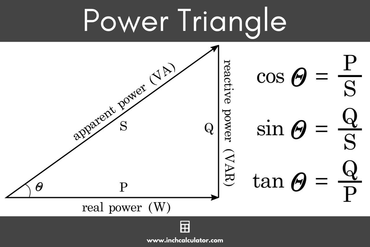
The power factor of a 3 phase motor is defined as the cosine of the phase angle between the phase voltage and the phase current, representing the ratio of active real power to total apparent power in the electrical circuit.
Introduction to Electrical Power in Three-Phase Systems
Understanding how electrical energy is converted into mechanical work inside industrial and commercial settings requires looking closely at how alternating current (AC) behaves. A three-phase motor is the workhorse of modern industry, driving pumps, compressors, conveyors, and heavy manufacturing machinery. Yet, operating these large inductive loads efficiently demands an understanding of power quality parameters. Among these metrics, power factor stands out as a critical indicator of electrical efficiency and grid utilization.
When evaluating electrical systems, technicians and engineers frequently encounter terms like active power, reactive power, and apparent power. The interplay between these components dictates the overall power factor of a 3 phase motor. Rather than being a fixed constant, this value fluctuates based on the motor's operating load, design characteristics, and supply voltage conditions. Grasping the exact definition of power factor for a 3 phase motor allows facility managers to optimize energy consumption, reduce utility penalties, and extend the operational lifespan of heavy-duty electrical assets.
Core Definition of Power Factor
At its most fundamental level, the power factor (PF) of a 3 phase motor is the ratio of real power ($P$, measured in kilowatts, kW) to apparent power ($S$, measured in kilovolt-amperes, kVA). Mathematically, this is expressed as:
$$\text{Power Factor (PF)} = \frac{\text{Real Power } (P)}{\text{Apparent Power } (S)}$$
In a purely resistive circuit, voltage and current wave forms are completely in phase, meaning the peaks and zero-crossings align perfectly, resulting in a power factor of 1.0 (or unity). However, three-phase induction motors rely on electromagnetic fields to operate. Creating these rotating magnetic fields requires inductive reactance, which introduces a time delay between the voltage and the current. Consequently, the current waveform lags behind the voltage waveform.
This phase shift is represented by the Greek letter theta ($\theta$). Therefore, the power factor is also mathematically defined as the cosine of this phase angle ($\cos\theta$). In a balanced three-phase system, the calculations can be performed on a per-phase basis or evaluated using total system values:
$$P = \sqrt{3} \times V_L \times I_L \times \cos\theta$$
Where $V_L$ is the line-to-line voltage, $I_L$ is the line current, and $\cos\theta$ is the power factor. This relationship highlights that for a given amount of mechanical work (real power), a lower power factor requires a higher total current to flow through the supply lines.
The Triad of Power: Real, Reactive, and Apparent Power
To fully comprehend the definition of power factor for a 3 phase motor, one must examine the three distinct components of AC power that form the "power triangle." These elements dictate how energy flows between the power source and the motor winding coils.
Real Power ($P$)
Real power, measured in watts (W) or kilowatts (kW), is the actual portion of electrical energy that is converted into useful mechanical work at the motor shaft. It represents the net energy consumed to overcome friction, turn the rotor, and drive the connected mechanical load.
Reactive Power ($Q$)
Reactive power, measured in volt-amperes reactive (VAR) or kilovars (kVAR), does not perform useful work. Instead, it is continuously cycled back and forth between the power supply and the motor's magnetic circuits. Induction motors require reactive power to establish and sustain the rotating magnetic field within the stator and rotor iron core. While it does not register on a traditional billing meter as consumed energy, it places an extra burden on the distribution transformers and conductors.
Apparent Power ($S$)
Apparent power, measured in volt-amperes (VA) or kilovolt-amperes (kVA), is the vector sum of real power and reactive power. It represents the total capacity that the electrical supply system must deliver to satisfy the motor's combined real and reactive power demands.
| Power Type | Unit of Measurement | Function in a 3 Phase Motor |
|---|---|---|
| Real Power ($P$) | Kilowatts (kW) | Performs actual mechanical work at the shaft. |
| Reactive Power ($Q$) | Kilovars (kVAR) | Builds and maintains magnetic fields in the motor. |
| Apparent Power ($S$) | Kilovolt-Amperes (kVA) | Total vector power demanded from the electrical supply. |
Why Induction Motors Exhibit Low Power Factors
Unlike synchronous motors, which can be adjusted to operate at unity power factor or even provide leading reactive power, standard three-phase induction motors are inherently lagging inductive loads. The primary driver of this characteristic is the air gap separating the stator and the rotor.
To transfer energy magnetically from the stator windings to the rotor bars, an excitation current is required. This magnetizing current is largely reactive, meaning it creates the magnetic flux without directly contributing to shaft rotation. When a 3 phase motor runs at full load, the real power component is high, overshadowing the fixed magnetizing component, resulting in a relatively healthy power factor—typically between 0.85 and 0.92 depending on the motor size and design class.
However, when the motor operates under light loads or no load, the real power drops significantly while the magnetizing current remains nearly constant. Because the reactive power requirement stays relatively stable regardless of the mechanical load, the ratio of real power to apparent power worsens. At 25% load, for instance, a standard induction motor's power factor can drop sharply to 0.50 or lower, increasing relative line currents and system losses.
Operational Impacts of a Poor Power Factor
Operating a 3 phase motor installation with a consistently low power factor introduces several technical and financial challenges for industrial facilities and commercial buildings.
Increased Current Draw and Thermal Stress
Because apparent power is higher relative to real power when the power factor drops, higher current must flow through the same gauge of cables. According to Joule's law ($P = I^2R$), electrical losses in conductors increase proportionally with the square of the current. This excess current generates additional heat in motor windings, supply cables, and distribution transformers, accelerating insulation degradation and shortening equipment life.
Voltage Drop and Regulation Issues
High current flowing through system impedances causes excessive voltage drops across distribution lines. Low voltage at the motor terminals can lead to sluggish starting performance, overheating, and nuisance tripping of protective thermal overloads.
Utility Penalties and Capacity Constraints
Commercial and industrial electricity providers monitor power factor closely. Many utilities impose reactive power penalties or demand charges on facilities that allow their aggregate power factor to fall below a specified threshold, such as 0.90 or 0.95. Furthermore, a low power factor consumes valuable capacity within local transformers and switchgear, limiting the facility's ability to add new equipment without costly infrastructure upgrades.
Methods for Improving and Managing Power Factor
Given the drawbacks of operating with lagging power factors, facility engineers employ several standardized strategies to optimize the electrical efficiency of 3 phase motor systems.
Proper Motor Sizing and Selection
One of the most effective ways to maintain a high power factor is to avoid oversizing motors. Selecting a motor whose rated capacity closely matches the mechanical load ensures it operates closer to its optimal loading zone (typically 75% to 100% of rated capacity) where the power factor is naturally maximized.
Installation of Capacitor Banks
Static shunt capacitors are widely deployed to counteract the lagging reactive power demanded by induction motors. Capacitors draw leading reactive current, which neutralizes the lagging reactive current required by the motor's magnetic fields. This local compensation reduces the total apparent power drawn from the utility grid, relieves stress on upstream transformers, and lowers utility penalty charges.
Utilization of Variable Frequency Drives (VFDs)
Modern adjustable speed drives (VFDs) rectify incoming AC power to DC and then invert it back to a controlled AC frequency and voltage. While the front-end diode bridge of standard VFDs can introduce harmonic distortion, modern units with active front ends or built-in DC-link reactors help maintain a high displacement power factor across varying motor speeds.
Frequently Asked Questions
Can the power factor of a 3 phase motor exceed 1.0?
No. In passive AC circuits containing resistance and reactance, the power factor is defined as the cosine of the phase angle ($\cos\theta$), which cannot exceed 1.0 (unity). While synchronous motors can operate at a leading power factor when over-excited, standard three-phase induction motors always operate at a lagging power factor between 0 and 1.0.
How does motor load affect the power factor?
The power factor varies directly with the mechanical load applied to the motor shaft. At full load, the power factor is at its highest operating level. As the mechanical load decreases toward zero, the real power consumption drops while the magnetizing reactive power remains nearly constant, causing the overall power factor to degrade significantly.
What is the difference between displacement power factor and true power factor?
Displacement power factor measures the phase shift between the fundamental voltage and current waveforms. True power factor accounts for both this phase displacement and the presence of harmonic distortions introduced by electronic controllers like VFDs, representing the ratio of total real power to total apparent power.
Why do utilities penalize low power factor?
Utilities must supply both real power (which generates revenue through kilowatt-hour billing) and apparent power (which dictates the physical sizing of generators, transmission lines, and transformers). A low power factor means the utility must maintain larger infrastructure to deliver the same amount of useful work, increasing operational costs.
Are there standard efficiency classes for 3 phase motors regarding power factor?
Yes, international standards such as IEC 60034-30-1 and NEMA MG 1 classify motors by energy efficiency levels (e.g., IE3 Premium Efficiency). While efficiency ratings focus primarily on minimizing internal losses, higher-efficiency motors are typically designed with optimized electromagnetic geometries that also yield improved full-load power factors compared to older legacy designs.
Conclusion and Recommended Next Actions
The power factor of a 3 phase motor is a crucial technical metric defined as the ratio of real power to apparent power, or the cosine of the phase angle between voltage and current. Recognizing how this parameter changes under varying mechanical loads enables facility operators to make informed decisions regarding asset sizing and electrical design. To optimize system performance, conduct a comprehensive power quality audit using a true-RMS power analyzer to measure existing motor loads, evaluate whether facility motors are properly sized, and consult with a licensed electrical engineer to determine if localized capacitor correction banks or modern drive upgrades are necessary to eliminate utility penalties and improve overall electrical efficiency.