Mastering SAP2000 is a critical competency for structural engineers aiming to perform complex linear and nonlinear static and dynamic analysis. By focusing on fundamental modeling techniques, advanced material nonlinearities, and result verification, these seven essential tutorials provide a structured pathway to professional proficiency in structural simulation and design optimization.
The Foundation: Structural Modeling and Geometry Definition
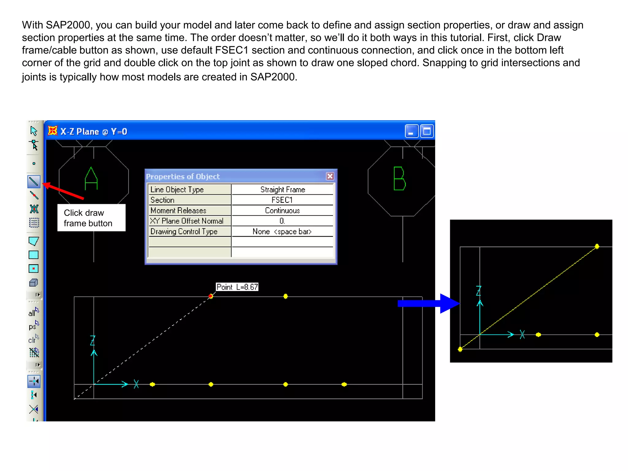
The first step in any SAP2000 workflow is the precise definition of structural geometry. For many engineers, the transition from basic CAD drafting to FEA (Finite Element Analysis) modeling involves a steep learning curve regarding coordinate systems, grid lines, and element connectivity. An essential tutorial for this phase focuses on utilizing the SAP2000 drawing tools alongside the import features for DXF or IFC files.
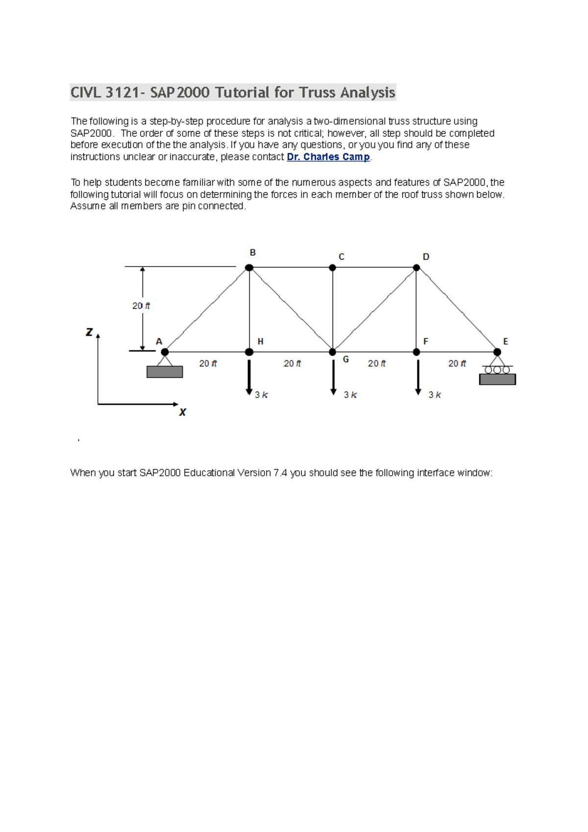
Proper modeling starts with the "Coordinate System" configuration. Engineers must understand the difference between Global and Local axes. The local axes (1, 2, 3) define the orientation of beam, column, and shell elements, which dictates how the software interprets forces and moments. A high-quality tutorial will walk you through defining a grid system, establishing story heights, and correctly assigning joint constraints (pinned, fixed, or roller) to ensure the structure has appropriate degrees of freedom. Avoid the common mistake of ignoring the "Auto-Merge" tolerance; if joint points do not overlap perfectly within the model, the structural stiffness matrix will contain singularities, leading to errors during the analysis phase.
Mastering Section Properties and Material Assignments
Once the skeleton is defined, the assignment of section properties and material behavior is paramount. SAP2000 requires accurate input for Young’s Modulus, Poisson’s ratio, and density. A core tutorial in your training should focus on the "Section Designer" utility. This tool allows engineers to define non-standard or composite sections by combining various shapes and materials.
When modeling concrete, you must specify the correct reinforcement ratios and confinement factors, as these directly influence the plastic hinge properties in nonlinear analysis. For steel structures, tutorials should emphasize the importance of defining the "Section Properties" library. Ensure you are selecting the correct profile designations from international databases (AISC, Eurocode, etc.) to ensure that the cross-sectional area, moment of inertia, and section modulus values align with regional building codes. Failure to verify these properties leads to inaccurate deflection and stress results, even if the load application is correct.
Load Pattern Definition and Combinations
A structural model is only as useful as the load cases applied to it. Engineers often struggle with the transition between "Load Patterns," "Load Cases," and "Load Combinations." A comprehensive tutorial on this topic is essential because it distinguishes between the static nature of gravity loads and the time-dependent nature of dynamic events.
You should practice creating dead load, live load, snow, wind, and seismic patterns. The key here is the "Auto-Lateral Load" function. SAP2000 provides built-in tools to calculate seismic forces based on specific building codes—such as ASCE 7-22—by inputting parameters like the site soil class, spectral response acceleration coefficients, and the response modification factor (R). Understanding how to set up "Load Combinations" according to LRFD (Load and Resistance Factor Design) or ASD (Allowable Stress Design) is the difference between a compliant structure and a failed one. Always verify your load paths by checking the "Reaction Forces" in a simple cantilever or beam model before advancing to complex multi-story structures.
Linear and Nonlinear Static Analysis Techniques
Linear static analysis is the workhorse of structural engineering, yet nonlinear static (pushover) analysis is required to understand the actual capacity of a building beyond its elastic limit. A tutorial focusing on "Static Pushover Analysis" is vital for engineers dealing with seismic retrofitting or performance-based design.
In a pushover analysis tutorial, you will learn to define plastic hinges at the ends of beams and columns. These hinges represent the points where the structure undergoes inelastic deformation. The tutorial should explain how to monitor the "Base Shear vs. Roof Displacement" curve. This curve tells you when the structure reaches its yield point and when it reaches collapse. It is crucial to understand that nonlinear analysis is an iterative process; if the model fails to converge, you must adjust the "Load Control" parameters or refine the mesh density of your shell and frame elements to ensure numerical stability.
Dynamic Analysis: Response Spectrum and Time History
When static analysis is insufficient, dynamic analysis is mandatory. This includes Response Spectrum Analysis (RSA) and Time History Analysis (THA). An essential tutorial will guide you through the modal analysis process, explaining the participation factors—the percentage of mass participating in each mode of vibration.
For RSA, you will learn to input a response spectrum function based on the seismic design category of your location. The tutorial should demonstrate how to combine modal responses using the CQC (Complete Quadratic Combination) or SRSS (Square Root of the Sum of the Squares) methods. Time History Analysis, while computationally expensive, is the most accurate way to simulate a ground motion. You will need to import acceleration-time data from actual earthquake records. A critical skill taught in these tutorials is "Scaling": ensuring your time history record is appropriately matched to your design response spectrum to meet code-required safety levels.
Result Verification and Graphical Interpretation
Modeling is prone to "Garbage In, Garbage Out." Therefore, a tutorial on post-processing and verification is the most important for ensuring engineering safety. You must know how to visualize deformed shapes, bending moment diagrams, and shear force diagrams.
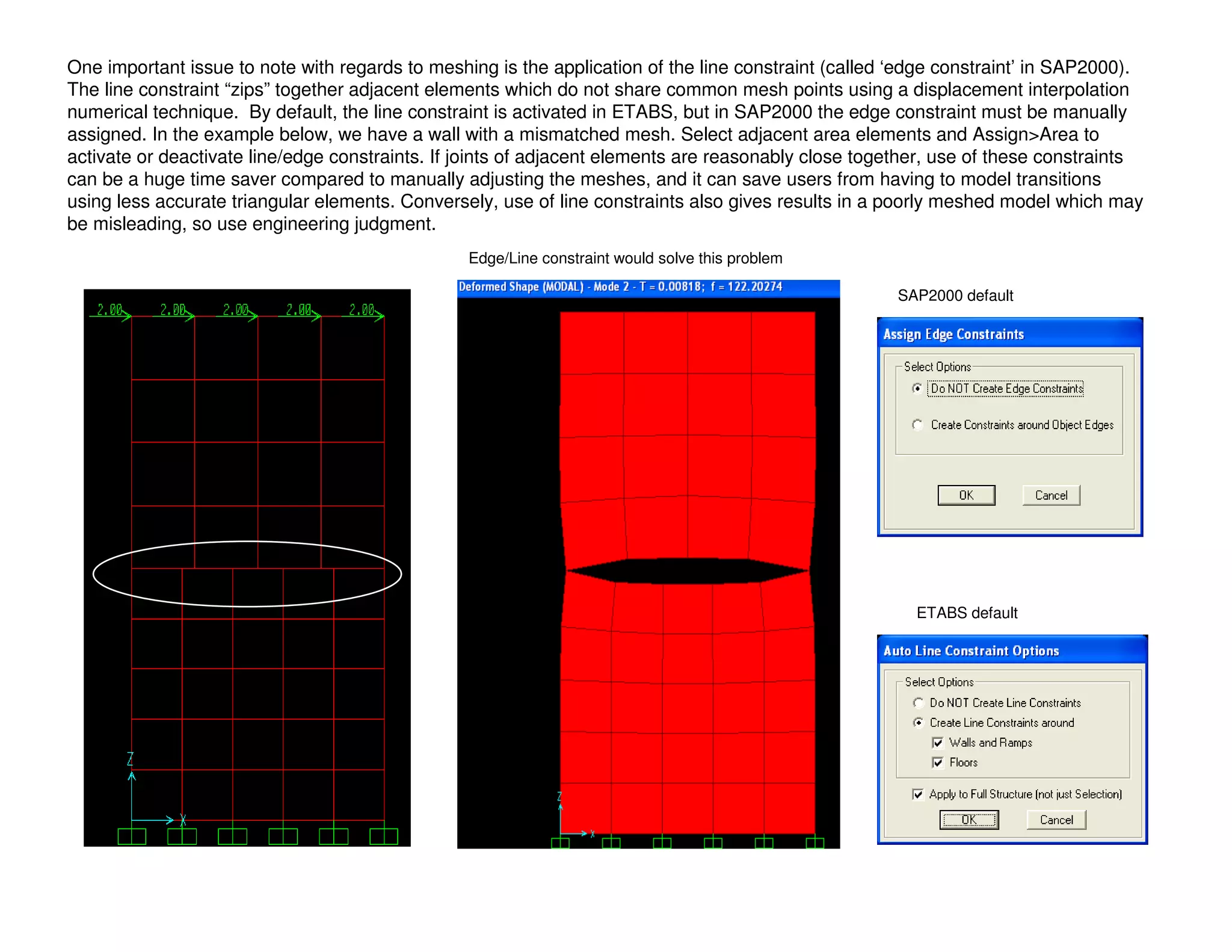
Check for "Discontinuity." If a bending moment diagram jumps unnaturally or a frame element shows zero stress where it should show maximum stress, you have likely modeled a connection incorrectly. Use the "Table Export" feature to verify your results against hand calculations for simple structures. Additionally, learn to interpret "Stress Contours" in shell elements. If you see high-stress concentrations in localized areas (stress singularities), consider refining your mesh. A professional engineer always cross-references SAP2000’s graphical output with analytical checks to ensure the equilibrium of the global system is maintained.
Advanced Modeling: Soil-Structure Interaction
The final essential tutorial covers Soil-Structure Interaction (SSI). Most engineers treat the base of their building as fixed, but in reality, the soil provides spring-like support that influences the structure’s natural period. Using "Link Elements" to represent soil springs (subgrade modulus) is an advanced skill that significantly increases the accuracy of your seismic assessments.
This tutorial should explain how to calculate the spring stiffness coefficients (k) based on soil properties provided in a geotechnical report. By replacing fixed supports with these link elements, you allow the structure to undergo foundation rocking and translation. This often results in a more realistic distribution of base shear and moment, often leading to more efficient foundation designs. Understanding this concept is the hallmark of a senior structural engineer capable of managing complex site-specific constraints.
Comparison of SAP2000 Analysis Types
| Analysis Type | Primary Purpose | Computational Demand | Key Metric |
|---|---|---|---|
| Linear Static | Standard gravity/wind design | Very Low | Stress/Deflection |
| Linear Dynamic | Code-based seismic design | Moderate | Modal Periods |
| Nonlinear Static | Performance-based retrofit | Moderate | Hinge Rotation |
| Nonlinear Dynamic | Site-specific hazard assessment | High | Peak Ground Displaccement |
Frequently Asked Questions
1. How do I troubleshoot non-convergence in SAP2000? Non-convergence often results from numerical instability due to sudden stiffness changes. Check your model for "zero-stiffness" members or unconnected nodes. In nonlinear analysis, decrease the step size in the "Nonlinear Parameters" menu to allow the solver to handle the geometric or material nonlinearity more smoothly.
2. Is it necessary to perform hand calculations alongside SAP2000? Yes. While SAP2000 is powerful, it is a tool. Code of practice requires engineers to verify the validity of software output. Always perform simplified hand checks (e.g., tributary area method) to ensure the magnitude of the software results is reasonable and reflects the structural reality.
3. Which international design codes are supported in 2026? As of 2026, SAP2000 supports a vast library of international standards including the latest editions of ASCE 7, ACI 318, AISC 360, Eurocodes (EN 1991-1998), and various national annexes. Always verify your specific project requirements against the software's "Design Preferences" menu to ensure the correct code edition is active.
4. Can SAP2000 handle large-scale BIM integration? Yes. SAP2000 features robust API and import/export capabilities, particularly with IFC (Industry Foundation Classes) and Revit files. However, direct imports often require manual cleanup of connectivity and section definitions to ensure the FEA model is structurally sound for analysis.
5. What is the difference between an Frame and a Shell element? Frame elements are one-dimensional objects defined by a cross-section used for beams, columns, and braces. Shell elements are two-dimensional areas used for walls, slabs, and diaphragms. Understanding this distinction is critical because shells can resist in-plane and out-of-plane forces, whereas frames primarily resist axial and bending loads.
6. How do I optimize a structure in SAP2000? Use the "Auto-Select List" feature in the section properties menu. You can group a variety of potential steel sections into a single list, and upon running the analysis and design, SAP2000 will automatically select the lightest section that satisfies all strength and serviceability limit state requirements.
Next Steps for Engineers
To solidify these skills, identify a past project you completed using manual methods or a simpler software package. Re-model this structure in SAP2000, applying the lessons learned from the seven tutorials outlined above. Validate your results against your original findings. For complex dynamic tasks, consider participating in specialized workshops hosted by Computers and Structures, Inc. (CSI), which provide the most current procedural documentation for the 2026 version of the software. Always prioritize professional judgment; software provides the analysis, but the engineer provides the design.