Installing a 3-way dimmer switch involves replacing one of the two existing switches that control a single light fixture from different locations. By identifying the "common" wire and correctly connecting it alongside the two traveler wires to the new dimmer, you can achieve precise lighting control while maintaining the convenience of dual-location switching.
Understanding the Mechanics of a 3-Way Circuit
Before beginning the physical installation, it is essential to understand how a 3-way circuit operates. Unlike a standard single-pole switch, which simply opens or closes a single path for electricity, a 3-way system utilizes a pair of switches to control a load (the light fixture) from two different points, such as the top and bottom of a staircase or opposite ends of a hallway.
In a 3-way setup, the circuit consists of three primary wires: the common wire and two traveler wires. The common wire is the "hot" lead that either brings power from the electrical panel into the first switch or carries power from the second switch to the light fixture. The two traveler wires act as a bridge between the two switches. When you flip either switch, you are toggling the internal connection between the common terminal and one of the two traveler terminals. The light turns on when both switches are set to the same traveler path, completing the circuit.
When upgrading to a dimmer, you typically only replace one of the two switches with a 3-way dimmer unit. Standard analog dimmers are designed to work in tandem with a traditional 3-way on/off switch at the other location. However, if you desire dimming capabilities from both locations, you must purchase a specific digital or smart dimmer system that includes a "master" and a "remote" (or companion) unit designed to communicate electronically over the existing wiring.
Required Tools and Materials for 2026 Standards
As of 2026, electrical safety standards and tool efficiency have streamlined the DIY process. While basic tools remain the same, the precision of voltage detection and wire manipulation has improved. Ensure you have the following items before starting your project:
- 3-Way Dimmer Switch: Ensure it is rated for the total wattage of your fixture and compatible with your bulb type (LED, CFL, or Incandescent).
- Non-Contact Voltage Tester: This is the most critical safety tool to confirm that power is fully disconnected before you touch any wires.
- Phillips and Flat-Head Screwdrivers: Most switch terminals use "tri-drive" screws, but a standard set is usually sufficient.
- Wire Strippers: Necessary if your existing wires are damaged or if you need to expose fresh copper for a more secure connection.
- Needle-Nose Pliers: Used for looping wire ends around terminal screws.
- Electrical Tape or Wire Labels: Essential for marking the "common" wire during the transition.
- Wire Nuts or Lever Connectors: Lever connectors (such as Wago-style clips) have become the industry preference in 2026 for their security and ease of use compared to traditional twist-on wire nuts.
Verification of Bulb and Dimmer Compatibility
One of the most common failures in dimmer installation is a mismatch between the switch and the light source. In 2026, high-efficiency LED lighting is the standard, but not all LEDs are dimmable. Installing a dimmer on a non-dimmable LED bulb will result in shortened bulb life, audible buzzing, or aggressive flickering.
Check the packaging of your light bulbs to confirm they are labeled as "Dimmable." Furthermore, ensure your dimmer is a "C-L" or Universal model, which is specifically engineered to handle the unique electrical signatures of LED and CFL loads. Traditional dimmers designed for incandescent bulbs often fail to provide enough current to keep an LED stable at low light levels, leading to "drop-out" (where the light shuts off before reaching the bottom of the slider) or "pop-on" (where the light won't turn on until the slider is pushed significantly upward).
Many modern dimmers also feature a low-end trim adjustment. This is a small hidden dial or a programming sequence that allows you to set the minimum voltage the dimmer sends to the bulb. Adjusting this is crucial for preventing flickering at the lowest brightness settings.
Step-by-Step Installation Procedure
1. Power De-energization and Safety Confirmation
Locate your home's main electrical panel and identify the circuit breaker controlling the light fixture. Switch the breaker to the "Off" position. Return to the light switch and attempt to turn the light on and off to verify the correct breaker was pulled.
Once the light remains off, unscrew the wall plate and the switch mounting screws. Carefully pull the switch out from the box, exposing the wires. Use your non-contact voltage tester to check every wire in the box. The tester should not beep or light up. If it does, power is still present, and you must check other breakers.
2. Identifying and Labeling the Common Wire
This is the most technical part of the installation. A 3-way switch has three screw terminals (excluding the green ground screw). One screw is a different color than the other two—usually a darker brass or black color. This is the Common (Point) Terminal.
Before disconnecting any wires, identify the wire attached to this dark screw. Wrap a piece of electrical tape around this wire or use a label to mark it as "Common." The other two wires attached to the lighter-colored screws are the travelers; their position relative to each other does not matter, but the common wire must be correctly identified for the new dimmer to function.
3. Disconnecting the Old Switch
Loosen the terminal screws and remove the wires. If the wires were connected via "back-stabbing" (pushed into small holes in the back of the switch), you may need to insert a small screwdriver into the release slot or simply cut the wires and strip back 1/2 inch of new insulation. Ensure the copper ends are clean and straight.
4. Wiring the New 3-Way Dimmer
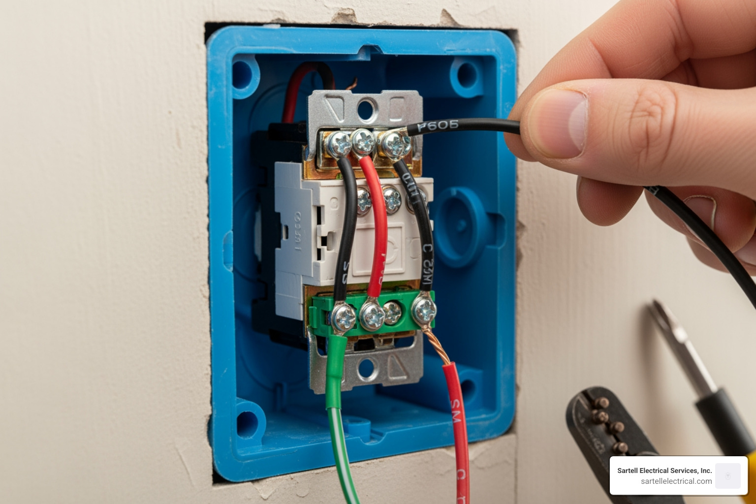
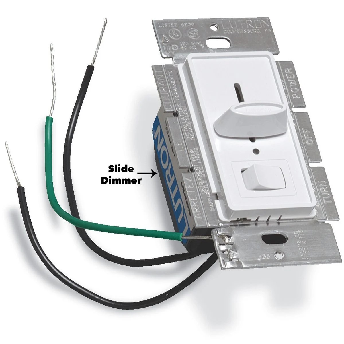
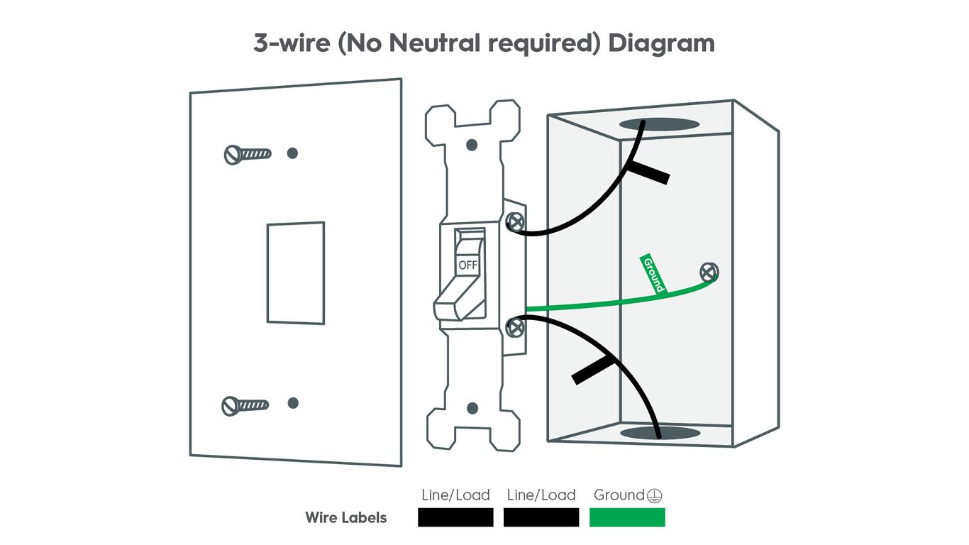
Most 3-way dimmers come with pre-attached wire leads (pigtails) or screw terminals. Follow the manufacturer’s specific wiring diagram, but the standard configuration is as follows:
- The Ground Wire: Connect the bare copper or green wire from the wall box to the green screw or green wire on the dimmer.
- The Common Wire: Connect the wire you labeled "Common" to the black or "common" labeled wire/terminal on the dimmer.
- The Traveler Wires: Connect the two remaining wires (the travelers) to the two traveler wires/terminals on the dimmer (usually red or gold). The order of these two wires is interchangeable.
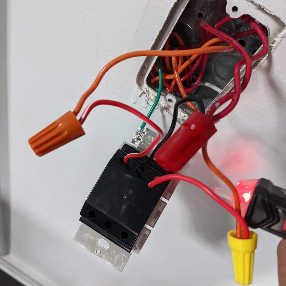
If you are using lever connectors, simply insert the corresponding wires into the ports and snap the levers shut. If using wire nuts, twist the wires together clockwise until they are tight and cannot be pulled apart.
5. Mounting and Testing
Carefully fold the wires back into the electrical box. Avoid pinching the wires against the back of the box or the sides of the dimmer. Secure the dimmer to the box with the provided mounting screws. Do not replace the wall plate yet.
Restore power at the circuit breaker. Test the dimmer by sliding it through its full range. Then, go to the second switch in the 3-way circuit and flip it. The light should toggle on or off regardless of the dimmer's position. If the light only works when the other switch is in one specific position, you have likely swapped the common wire with one of the travelers.
Dimmer Performance Comparison Table
The following table outlines the differences between various dimming technologies available in 2026 to help you determine if a standard 3-way installation meets your needs.
| Feature | Standard Analog 3-Way | Digital Multi-Location | Smart Wi-Fi/Matter Dimmer |
|---|---|---|---|
| Dimming Range | 10% - 100% | 1% - 100% | 1% - 100% (App Controlled) |
| Control Points | Dim from 1 spot, On/Off from 2 | Dim from all spots | Dim from all spots + Voice/Phone |
| Neutral Required | Rarely | Sometimes | Almost Always |
| Installation Difficulty | Low | Moderate | Moderate to High |
| Best For | Kitchens, Hallways | Master Bedrooms | Home Automation Enthusiasts |
| Cost (2026 Est.) | $15 - $25 | $40 - $60 | $35 - $75 |
Troubleshooting Common Installation Issues
Even with careful planning, electrical projects can encounter hurdles. Here are the most frequent issues found in 3-way dimmer setups:
The Light Flickers at Low Levels
This is usually a bulb compatibility issue or a trim setting requirement. Most 2026 dimmers have a "Low-End Trim" adjustment. Locate the small wheel or programming button (refer to your specific manual) and increase the minimum power until the flickering stops. If the flickering persists, ensure the bulbs are explicitly labeled as "Dimmable."
The Switch Only Works When the Other Switch is "On"
This is the classic symptom of a misidentified common wire. If the common wire is accidentally placed on a traveler terminal, the circuit is broken whenever the other switch moves to the "wrong" traveler. To fix this, turn off the power, swap the wire on the common terminal with one of the traveler wires, and test again.
The Dimmer Gets Warm to the Touch
It is normal for dimmers to generate a small amount of heat as they dissipate energy to reduce light output. However, if the switch is uncomfortably hot, you may be exceeding the dimmer’s wattage rating. In 2026, this is rare with LEDs, but if you are using high-wattage halogen or incandescent bulbs, calculate the total load and ensure it is below the dimmer's maximum capacity (usually 150W for LED or 600W for incandescent).
The "Ghosting" Effect
Some high-sensitivity LED bulbs may glow slightly even when the dimmer is turned off. This happens because some dimmers bleed a tiny amount of current to power their internal circuitry or LED indicators. Using a higher-quality bulb or a dimmer that requires a neutral wire (which provides a dedicated return path for the switch's internal power) will typically solve this.
Frequently Asked Questions
Can I install a dimmer at both ends of a 3-way circuit?
With standard analog dimmers, the answer is no. Two analog dimmers on the same circuit will interfere with each other's voltage regulation, causing severe flickering or total circuit failure. If you want dimming at both ends, you must use a digital "Master/Remote" system or a smart switch system designed for multi-location dimming.
Why do some dimmers have a white wire while others do not?
A white wire on a dimmer usually indicates it requires a neutral connection. While traditional switches only "interrupt" the hot wire, modern smart dimmers and some high-end LED dimmers need a neutral wire to power their own internal chips and radios. If your electrical box does not have a bundle of white wires tucked in the back, you should look for a "No-Neutral Required" dimmer model.
Is it safe to use a 3-way dimmer on a single-pole circuit?
Yes, most 3-way dimmers are designed to be "universal" in this regard. If you are using it for a single-pole application (where only one switch controls the light), you simply connect the common wire and one of the traveler wires, leaving the second traveler terminal empty (and capped if it's a wire lead).
What should I do if my wires are all the same color?
In some older homes, all wires in the box might be black. In this case, identification is harder but possible. With the power on (and wires safely separated), use a multimeter to find the wire that has 120V of power relative to the ground. That is your common wire coming from the panel. If none have power, the common wire is at the other switch box, and you are currently at the "load" side where the common goes to the light.
How do I know if I need a Leading-Edge or Trailing-Edge dimmer?
Leading-edge dimmers are traditional and work best with incandescent bulbs. Trailing-edge dimmers (also known as ELV - Electronic Low Voltage) are more sophisticated and are generally better for LED drivers to prevent buzzing. Most 2026 "Universal" dimmers are designed to auto-detect or are optimized for the trailing-edge requirements of modern LEDs.
Final Recommendations
When choosing a dimmer in 2026, prioritize models that support the Matter or Thread protocols if you plan on integrating with a smart home system, as these offer the highest reliability and cross-platform compatibility. For a standard, non-smart installation, always opt for a "C-L" rated dimmer from a reputable manufacturer such as Lutron, Leviton, or Legrand.
Once your installation is complete and tested, ensure all wire connections are tight, as loose connections are a primary cause of electrical fires. If you encounter a wiring configuration that does not match the standard traveler/common setup—such as a "dead-end" 3-way where the power and light connections are in the same box—it is highly recommended to consult a licensed electrician to avoid short-circuiting the system or violating local building codes.
For further reading on electrical safety and local requirements, refer to the National Electrical Code (NEC) and ensure your hardware carries the UL (Underwriters Laboratories) or ETL safety certification mark.