Checking a 3-phase motor involves safety preparation, visual inspection, winding resistance testing using a multimeter, insulation resistance testing with a megohmmeter, and operational voltage and current verification under power to ensure proper mechanical and electrical balance.
Understanding the Fundamentals of 3-Phase Motors
A three-phase alternating current (AC) motor is a standard workhorse in industrial, commercial, and heavy residential settings. Renowned for their efficiency, self-starting capabilities, and rugged mechanical design, these motors rely on three separate alternating current supplies that reach their peak values at different times. This phase displacement creates a rotating magnetic field inside the stator, which induces a current in the rotor and causes it to turn.
When a three-phase motor fails, it usually does so in one of two ways: mechanical breakdown (such as bearing failure or shaft misalignment) or electrical degradation (such as winding insulation breakdown, a short circuit, or an open phase). Troubleshooting requires a methodical approach. By systematically checking the motor, technicians can prevent catastrophic failures, avoid unnecessary replacement costs, and minimize costly facility downtime.
Before picking up a tool, you must understand what normal looks like. Healthy stator windings should show balanced electrical resistance across all three phases. Furthermore, the insulation separating those copper windings from the grounded motor frame must remain entirely dry and intact. The following five-step process provides a reliable diagnostic blueprint used by professional electricians and maintenance technicians worldwide.
Step 1: Safety Preparation and Power Isolation
Electrical safety is the single most critical factor when diagnosing any rotating machinery. Because three-phase motors typically operate at higher voltages—ranging from 208V to 480V or higher in industrial environments—an arc flash or shock can be fatal. Never bypass safety protocols for the sake of speed.
The first action is to completely de-energize the motor by opening the main circuit breaker or disconnect switch. Apply a physical lockout/tagout (LOTO) device to ensure that no other worker can inadvertently re-energize the circuit while you are performing diagnostics. Once the switch is locked out, use a reliable, calibrated digital multimeter or voltage detector to test for voltage directly at the motor terminal box. Verify zero voltage across all phase-to-phase combinations ($L_1$ to $L_2$, $L_2$ to $L_3$, and $L_3$ to $L_1$) as well as phase-to-ground.
Finally, allow sufficient time for any attached variable frequency drives (VFDs) or large internal capacitors to discharge completely, and wait for the motor frame to cool down if it has been running under a heavy load. Personal protective equipment (PPE), including safety glasses, electrically rated gloves, and arc-rated clothing, must be worn according to the specific voltage class of the equipment.
Step 2: Visual and Mechanical Inspection
Many motor faults present physical symptoms long before they trigger an electrical fault code. A thorough visual and mechanical inspection can save hours of complex diagnostic testing by immediately revealing obvious structural or environmental damage.
Begin by inspecting the exterior of the motor housing. Look for signs of overheating, such as discolored, scorched, or blistered paint on the frame. Check the cooling fins for heavy accumulations of dirt, dust, or grease, which can trap heat and cause premature winding failure. Inspect the conduit box to ensure the cover is secure and that moisture or oil has not leaked inside the terminal compartment.
Next, check the mechanical integrity of the motor:
- Shaft Play: Try to move the motor shaft radially and axially by hand. Excessive play indicates worn bearings that will soon cause the rotor to rub against the stator.
- Rotation: Spin the shaft manually. It should rotate smoothly without grinding noises, binding, or tight spots.
- Cooling Fan: Inspect the external cooling fan and its protective cover for cracks, blockages, or broken blades.
If the motor fails this physical inspection—such as exhibiting a seized bearing or a cracked housing—electrical testing becomes secondary, and mechanical overhaul or replacement is required.
Step 3: Winding Resistance Testing (Multimeter)
Electrical winding tests check the internal health of the motor’s copper coils. The first electrical test is measuring winding resistance to detect open circuits, shorted turns, or high-resistance connections within the coils.
Disconnect the motor leads from the power supply or starter wiring to ensure you are testing only the motor windings, not the external cabling. Set your digital multimeter to its lowest ohms ($\Omega$) resistance range and zero the meter if required.
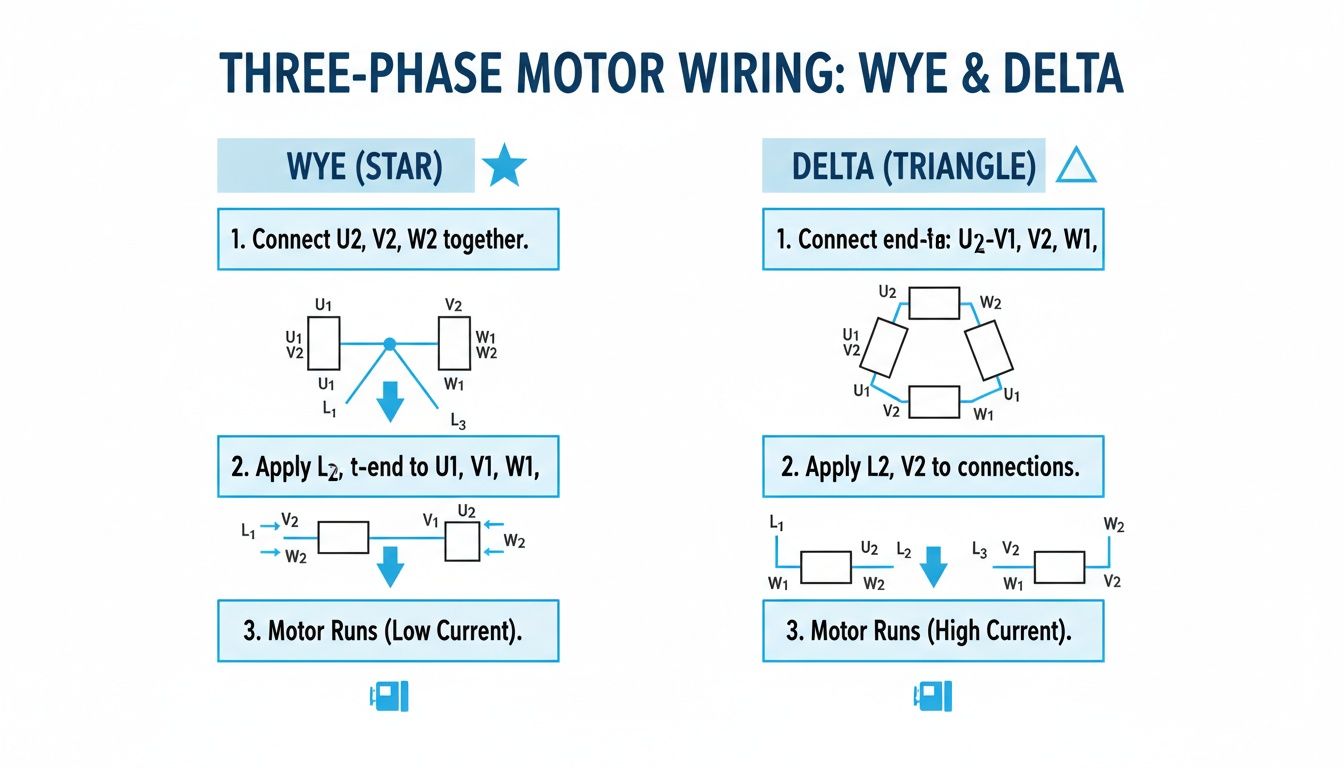
A standard three-phase motor has three distinct winding circuits, identifiable at the terminal block as $U1-U2$, $V1-V2$, and $W1-W2$ (or $T_1-T_4$, $T_2-T_5$, $T_3-T_6$ depending on the NEMA or IEC configuration). Measure the resistance across each individual winding pair and record your findings.
| Winding Pair | Measured Resistance ($\Omega$) | Expected Balance | Status |
|---|---|---|---|
| Phase A ($U_1$ to $U_2$) | Low fraction of an ohm | Within 1–2% of others | Normal |
| Phase B ($V_1$ to $V_2$) | Low fraction of an ohm | Within 1–2% of others | Normal |
| Phase C ($W_1$ to $W_2$) | Low fraction of an ohm | Within 1–2% of others | Normal |
The golden rule of winding resistance testing is balance. Because the three phases are wound identically, the resistance values across all three phases must be virtually identical—typically within 1 to 2 percent of one another. If one phase shows significantly lower resistance, it indicates a shorted turn (windings touching each other prematurely). If a phase shows infinite resistance (OL on the meter), you have an open circuit (a broken wire).
Step 4: Insulation Resistance Testing (Megohmmeter)
While a standard multimeter checks for continuity and low-resistance shorts, it cannot detect insulation breakdown because its internal battery voltage (usually 9V) is too low. To verify that the electrical insulation between the copper windings and the grounded iron motor frame is sound, you must use a megohmmeter (frequently referred to as a "megger").
A megohmmeter applies a high direct-current (DC) test voltage—typically 500V or 1000V for standard low-voltage motors—and measures the resulting high resistance in megaohms ($M\Omega$).
To perform this test:
- Ensure all motor leads are disconnected from one another and from ground.
- Set the megohmmeter to the appropriate test voltage corresponding to the motor's operating voltage rating.
- Connect the earth lead of the megohmmeter to bare, unpainted metal on the motor frame (ground).
- Touch the line probe to each motor terminal ($U_1$, $V_1$, and $W_1$) sequentially for at least 60 seconds.
[Megohmmeter Test Setup] (+) High Voltage Probe ---> Motor Terminal (U1, V1, or W1) (-) Earth/Ground Lead ---> Motor Frame / Ground Screw
Evaluate the readings against industry standards, such as IEEE 43 guidelines. Generally, a healthy motor winding should exhibit an insulation resistance of at least several megaohms. A reading approaching zero indicates a dead short to ground, often caused by moisture, chemical contamination, or thermal degradation of the wire enamel. If the insulation resistance is unacceptably low, the motor must be dried out or rewound.
Step 5: Operational Voltage and Current Verification
If the motor passes all static bench tests (resistance and insulation), reconnect it to its power source, re-energize the circuit, and perform dynamic operational checks. Testing a motor while it is running under load reveals performance anomalies that static tests cannot uncover.
Use a digital multimeter to measure the line-to-line voltages while the motor is operating. The voltage across all three phases should be balanced. Voltage unbalance degrades motor efficiency, causes excessive internal heating, and can quickly destroy the stator. Calculate the voltage unbalance percentage using the standard NEMA formula: find the maximum deviation from the average voltage, divide it by the average voltage, and multiply by 100. Unbalance should never exceed 1 percent, or 2 percent in derated conditions.
Next, use a calibrated AC clamp meter to measure the current draw on each of the three supply lines ($L_1$, $L_2$, and $L_3$) while the motor is running its normal process load.
- Compare the measured current against the Full Load Amps (FLA) rating listed on the motor’s nameplate.
- The current across all three phases must be balanced. A current unbalance that is significantly higher than the voltage unbalance (often a ratio of 6 to 10 times) points directly to internal winding defects.
- If the operating current exceeds the nameplate FLA, inspect the driven mechanical equipment for binding, overloads, or alignment issues.
Common Troubleshooting Scenarios and Expert Guidance
Even with a structured 5-step checklist, technicians often encounter complex symptoms that require careful interpretation. Understanding how to connect physical test results to root causes prevents misdiagnosis.
Dealing with Tripped Overload Relays
If a motor starter trips repeatedly on overload, do not simply reset the relay and restart the motor. This is a symptom of an underlying issue. Check the operating current with a clamp meter (Step 5). If current is high across all three phases, the motor is mechanically overloaded or operating with low supply voltage. If current is unbalanced, suspect a single-phasing condition, loose terminal connections, or a failing winding.
The Impact of Variable Frequency Drives (VFDs)
When testing motors driven by VFDs, standard multimeters can sometimes give erratic voltage readings due to pulse-width modulation (PWM) high-frequency switching. Ensure your test instruments are True-RMS capable. Furthermore, VFD-driven motors require inverter-duty wire insulation to withstand voltage spikes; if an insulation test fails prematurely on a VFD application, verify that the drive's output filter settings and cable lengths comply with manufacturer specifications.
Frequently Asked Questions
Can I test a 3-phase motor with a standard digital multimeter?
Yes, a standard digital multimeter is sufficient for checking winding continuity, phase-to-phase resistance balance, and basic operational voltage. However, a standard multimeter cannot test winding insulation integrity because its internal battery voltage is too low to stress the insulation. For insulation testing, a dedicated megohmmeter is required.
What causes a 3-phase motor to run hot?
A 3-phase motor typically runs hot due to mechanical overload, restricted cooling airflow, high ambient temperatures, low supply voltage, or voltage unbalance between the phases. Voltage unbalance causes negative sequence currents to circulate in the rotor, generating excessive internal heat even if the average current appears normal.
What is the acceptable resistance difference between phases?
The resistance values measured across the three phases should match within 1 to 2 percent of each other. Because 3-phase windings are manufactured symmetrically, any noticeable deviation or imbalance indicates a shorted turn, a loose internal connection, or damaged winding coils.
How do I know if my motor is single-phasing?
Single-phasing occurs when one of the three power lines is lost due to a blown fuse, tripped breaker, or broken wire. A running motor subjected to single-phasing will experience a sudden drop in speed, a loud humming noise, severe vibration, and rapid overheating due to massive current spikes in the remaining two phases.
Do I need to disconnect the motor wires to test resistance?
Yes. You must disconnect the power leads from the motor terminal block before measuring winding resistance. Testing while connected to external wiring, control circuits, or starter components will result in inaccurate readings because the meter will measure the parallel resistance of the entire circuit.