Creating a reliable 3D print snap fit joint requires balancing material flexibility, geometrical clearance, beam length, and proper orientation to prevent layer shear failure. A successful snap fit relies on elastic deformation during assembly and returning to its original state once locked, demanding precise design considerations tailored to additive manufacturing constraints.
Understanding the Mechanics of 3D Printed Snap Fits
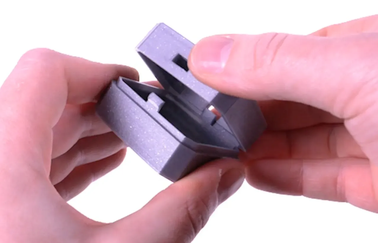
A snap fit is a mechanical joint system where a protrusion, such as a hook, bead, or ridge on one component, flexes temporarily during insertion into an undercut or mating cavity on a second component until it snaps securely into place. In traditional injection molding, snap fits are common because isotropic materials can bend predictably in multiple directions without cracking.
In additive manufacturing, however, the anisotropic nature of fused deposition modeling (FDM), stereolithography (SLA), and selective laser sintering (sintering) changes how parts behave under stress. Layers bonded together via heat or light typically represent the weakest structural plane. If a cantilever snap-fit beam is bent in a direction that forces the layer lines apart (interlayer shear), the joint is likely to snap or delaminate rather than flex elastically.
Therefore, understanding material elongation at break, yield strength, and layer adhesion is the foundation of designing functional snap fits. Designers must calculate deflection forces, optimize cantilever beam geometry, and incorporate proper draft angles to ensure longevity through multiple assembly and disassembly cycles.
Material Selection and Anisotropic Behavior
Different 3D printing filaments and resins exhibit vastly different mechanical properties. Choosing the wrong material can result in a snap fit that either permanently deforms (plastic deformation) on first use or shatters like glass under minor deflection.
FDM Materials (Filaments)
- PLA (Polylactic Acid): Rigid and easy to print, but has low impact strength and minimal elongation at break (typically 2% to 7%). PLA snap fits must be short and thick with minimal deflection angles; otherwise, they snap immediately.
- PETG (Polyethylene Terephthalate Glycol): Offers a balanced compromise between rigidity and flexibility. With higher elongation at break (around 50% to 80%) and excellent layer adhesion, PETG is one of the most reliable everyday materials for snap fits.
- ABS and ASA: Provide good impact resistance and thermal stability. They bend reasonably well before breaking, but printing them requires a heated enclosure to prevent warping and weak layer bonding, which compromises joint integrity.
- TPU (Thermoplastic Polyurethane): Highly flexible. While TPU makes incredible, virtually indestructible snap fits or living hinges, its high elasticity means joints can pull apart too easily under load unless designed with deep interlocks.
- Nylon: Excellent fatigue resistance, low friction coefficient, and high toughness. Nylon is arguably the best material for snap fits that need to be assembled and disassembled thousands of times, though it readily absorbs ambient moisture.
Resin Materials (SLA / MSLA)
Standard photopolymer resins are notoriously brittle, making them poor candidates for snap fits. Standard resin prints will often fracture under a tiny amount of angular deflection. To create functional snap fits in resin, engineers use specialized tough or flexible resins, or blend standard resin with small amounts of flexible additives to increase impact resistance.
Core Geometries of Snap Fit Joints
Snap fits generally fall into a few primary structural categories. Selecting the right geometry depends on whether the joint is meant to be permanent or detachable, and how much space is available inside the assembly.
| Snap Fit Type | Best Use Case | Primary Advantage for 3D Printing |
|---|---|---|
| Cantilever Snap Fit | Enclosures, electronics cases, modular panels | Predictable deflection, easy to orient flat |
| Annular Snap Fit | Caps, bottles, concentric cylindrical parts | Uniform 360-degree retention force |
| Torsion Snap Fit | Hinged lids, latches, heavy-duty opening mechanisms | Relies on twisting action rather than bending |
Cantilever Snap Fits
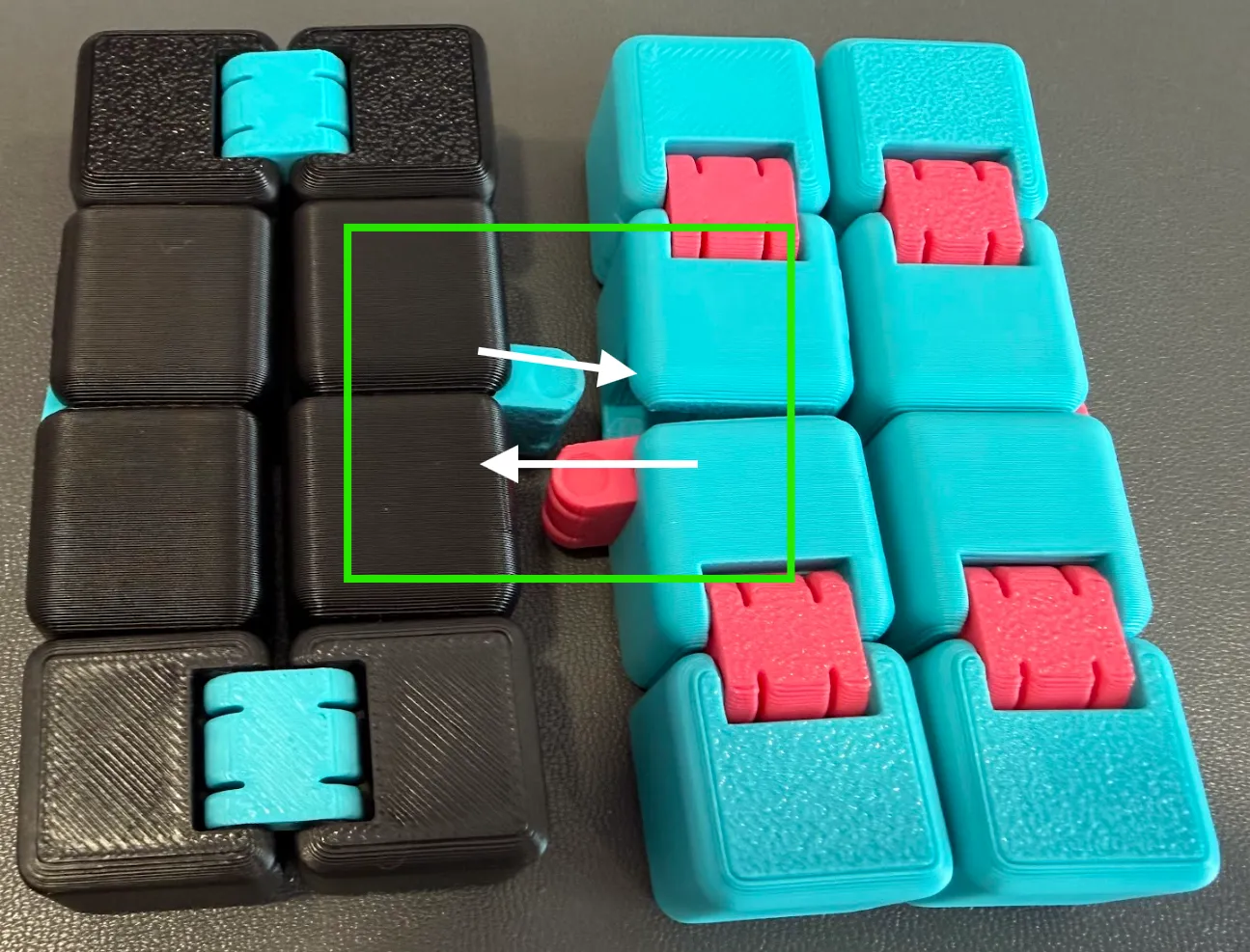
The cantilever beam is the most widely used configuration in 3D printing. One end of the beam is fixed to the main body, while the other end contains the protruding hook. When mating parts are pushed together, a ramp angle (typically 30 to 45 degrees) forces the beam to deflect outward. Once the hook clears the edge of the mating hole, the beam springs back into the undercut.
To design a successful cantilever snap fit:
- Taper the Beam: Tapering the width or thickness of the cantilever beam from the fixed base to the free end distributes the bending stress evenly along the entire length, preventing stress concentration points.
- Include a Radius: Sharp internal corners act as stress concentrators where cracks initiate. Always fillet the base of the cantilever beam with a generous radius.
- Manage the Return Angle: The locking face (the side that prevents the parts from pulling apart) should have a steep angle (between 75 and 90 degrees) to ensure a secure lock that resists accidental decoupling.
Annular Snap Fits
Annular snap fits involve continuous circular geometries, such as a snap-on bottle cap or a round lens cover. As the outer ring pushes over the inner ridge, the entire circumference expands outward uniformly.
For 3D printing, annular snap fits require careful printer calibration. If the printer is over-extruding or experiencing dimensional inaccuracy, the fit will either be impossibly tight or so loose that it falls off. A diametral clearance of 0.15 mm to 0.3 mm is typically required depending on the machine's tolerance capabilities.
Optimizing Print Orientation for Strength
Print orientation is the single most critical factor in determining whether a 3D printed snap fit survives. Because FDM parts are weakest along the Z-axis (interlayer adhesion), orienting a cantilever beam so that the bending force pulls the layers apart guarantees failure.
- Correct Orientation: Beam printed flat on bed
- Layers run lengthwise (Strong)
- Incorrect Orientation: Beam printed upright (vertical Z)
- Layers run crosswise (Weak delamination)
To maximize strength:
- Print Flat: Lay cantilever beams flat on the print bed so that the layers run parallel to the length of the beam. This ensures that when the beam bends, the tensile and compressive stresses are absorbed by continuous plastic extrusions rather than weak inter-layer bonds.
- Avoid Z-Axis Cantilevers: Never print a vertical snap-fit hook pointing upward along the Z-axis unless high-strength continuous fiber reinforcement is used.
- Support Placement: When designing the overhang for the hook undercut, angle the underside at 45 degrees or use a teardrop profile so the printer can bridge or form the geometry cleanly without requiring aggressive support material removal that might scar the mating surface.
Tolerances, Clearances, and Shrinkage
Achieving a snap fit that works right off the build plate requires accounting for material shrinkage and machine tolerances.
- Dimensional Clearance: Mating surfaces cannot have a nominal zero-clearance offset. A clearance gap of 0.2 mm to 0.4 mm between non-contacting walls ensures parts slide together smoothly without binding.
- Interference Depth: The depth of the undercut (how far the hook protrudes into the mating hole) should typically range from 0.5 mm to 1.5 mm for scale models and small enclosures. Anything deeper forces excessive strain on the plastic during assembly.
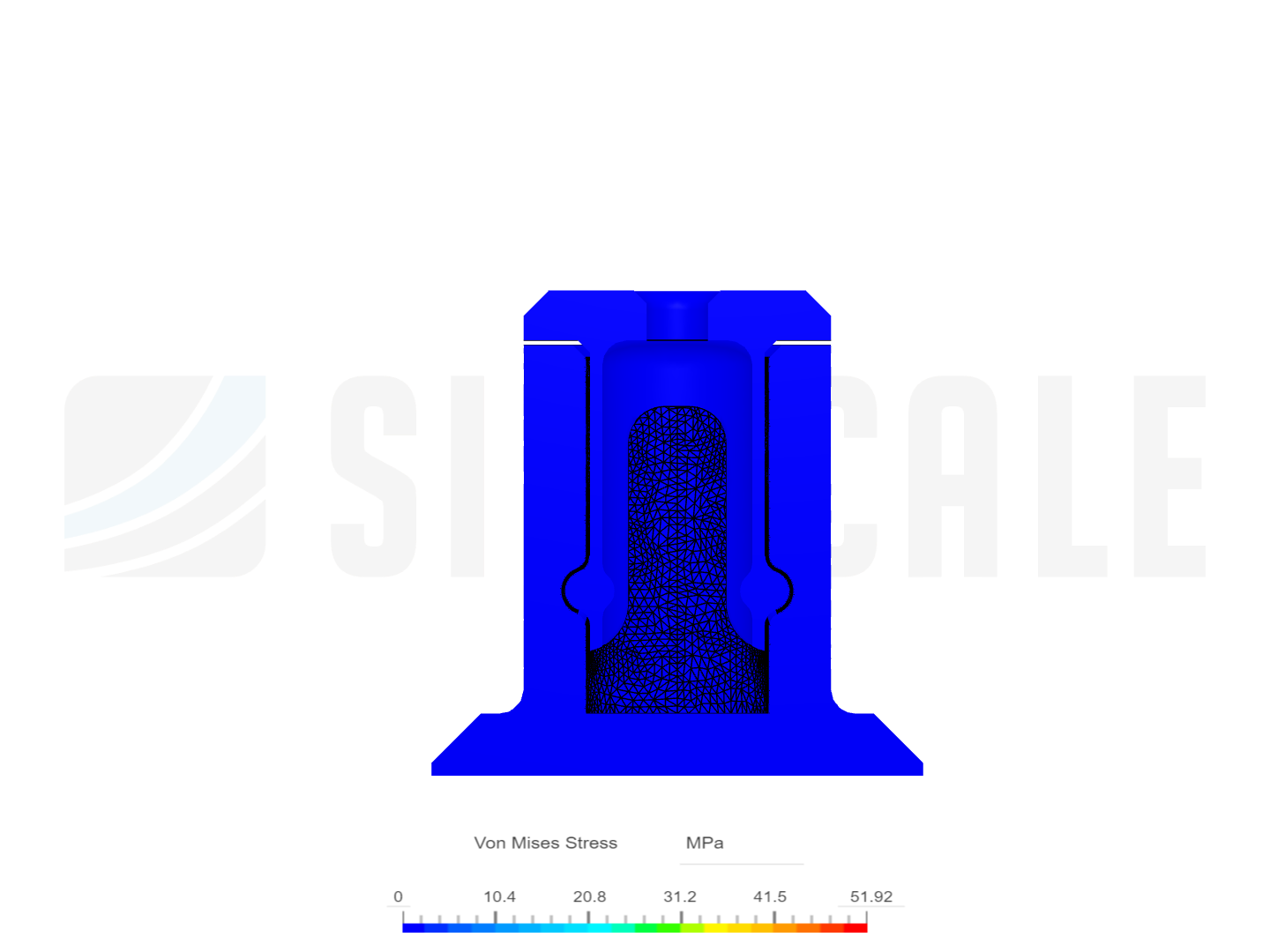
- Wall Thickness: Ensure the surrounding walls of the housing are thick enough to resist the outward reaction force of the snap fit. If the housing wall is too thin, the entire wall will flex outward instead of forcing the snap-fit beam to deflect, causing the joint to fail.
Post-Processing and Mechanical Testing
Even with optimal design, minor imperfections like stringing, z-seams, or slight elephant's foot on the first layer can interfere with snap-fit performance.
- Cleaning Seams: Inspect the Z-seam (where each layer starts and stops). If the slicer places a blob directly on the sliding ramp of the snap fit, use a hobby knife or fine sandpaper to smooth it out.
- Thermal Relief: For stiff materials like ABS, gently heating the snap fit with a heat gun or hair dryer immediately before assembly can help it seat without cracking, after which it cools into a permanent, stress-relieved locked state.
- Iterative Prototyping: Print a small test coupon containing only the snap-fit interface before committing to a 10-hour multi-part print. Testing the clip independently saves time and material.
Frequently Asked Questions
Why does my 3D printed snap fit keep breaking off?
Snap fits usually break because the print orientation forces bending stress across the layer lines (interlayer shear), or because the material is too brittle (like standard PLA or resin). Print the part flat on the build bed so layers run parallel to the beam length, and switch to a tougher material like PETG or Nylon.
What is the best filament for making snap fits that open and close repeatedly?
Nylon and PETG are the best standard FDM filaments for iterative cyclic loading. Nylon offers exceptional wear resistance and flexibility, while PETG provides a rigid snap with enough elastic yield to prevent snapping over hundreds of cycles.
How much clearance should I leave between snap-fit parts?
For non-contact sliding surfaces, a clearance of 0.2 mm to 0.3 mm works best for most well-calibrated FDM printers. For the interference depth of the actual hook, design an undercut of 0.5 mm to 1.0 mm depending on the length and thickness of the cantilever arm.
Can I design snap fits in SLA resin printing?
Yes, but standard resins are too brittle. To create functional resin snap fits, use specialized engineering resins classified as "tough," "ABS-like," or "flexible," and ensure wall thicknesses are slightly increased to handle the impact forces of snapping together.
How do I prevent my housing walls from bending instead of the snap fit?
If the housing wall surrounding the snap fit is thinner than the cantilever beam, the wall will absorb the deflection energy instead of the beam. Reinforce the housing perimeter with thicker walls, increased perimeters (walls/shells), or structural ribs.
Conclusion
Designing a successful 3D print snap fit requires a holistic approach that bridges CAD geometry, material science, and printer calibration. By prioritizing flat print orientations to leverage layer strength, selecting resilient filaments like PETG or Nylon, and designing tapered cantilever beams with proper fillet radii, you can produce durable, functional, and repeatable mechanical joints directly from your desktop 3D printer.