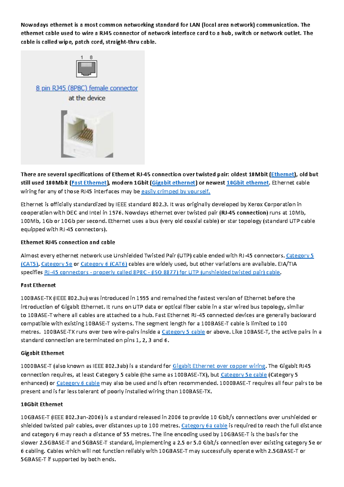
RJ45 cable wiring standards define the specific color-coded pinout configurations required to terminate twisted-pair Ethernet cables, ensuring reliable data transmission and compatibility across networking hardware. Adhering to the T568A and T568B standards is essential for maintaining signal integrity, preventing crosstalk, and ensuring that devices like routers, switches, and computers can communicate effectively within a local area network.
Understanding how to terminate an RJ45 connector—the standard modular connector used for Ethernet networking—requires familiarity with the TIA/EIA-568 standards. These standards dictate the sequence of the eight individual copper wires inside a Category 5e, 6, or 6a cable as they are inserted into the crystal-clear plastic connector. While there are two primary wiring schemes, the physical connector itself remains the same; the difference lies strictly in the arrangement of the wires, which determines the electrical path for data signals.
The Role of TIA/EIA-568 Standards
The Telecommunications Industry Association (TIA) and the Electronic Industries Alliance (EIA) established the TIA/EIA-568 standard to standardize the physical interface of networking equipment. Without these, every manufacturer might use different pinouts, leading to incompatible cables and chaotic infrastructure.
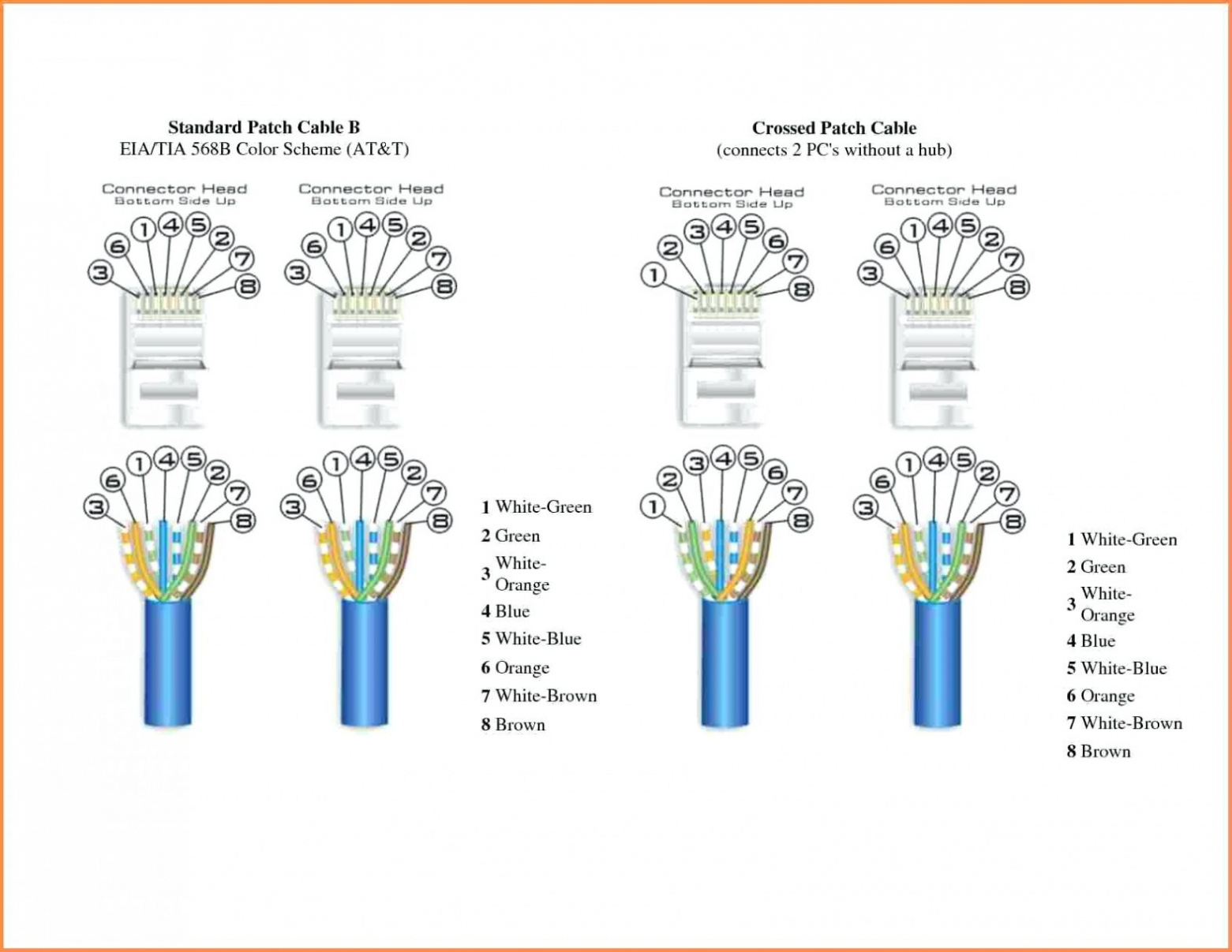
In modern networking, the goal is to match the pinout at both ends of a cable. If you use T568B at one end, you must use T568B at the other for a "straight-through" cable. This is the industry default for connecting a computer to a wall outlet or a router. Deviating from these standards or mixing them on a single cable (which creates a "crossover" cable) is rarely necessary in 2026, as modern Gigabit Ethernet hardware features Auto-MDIX (Automatic Medium-Dependent Interface Crossover), which automatically detects the wiring configuration and adjusts accordingly.
T568A vs. T568B: Decoding the Patterns
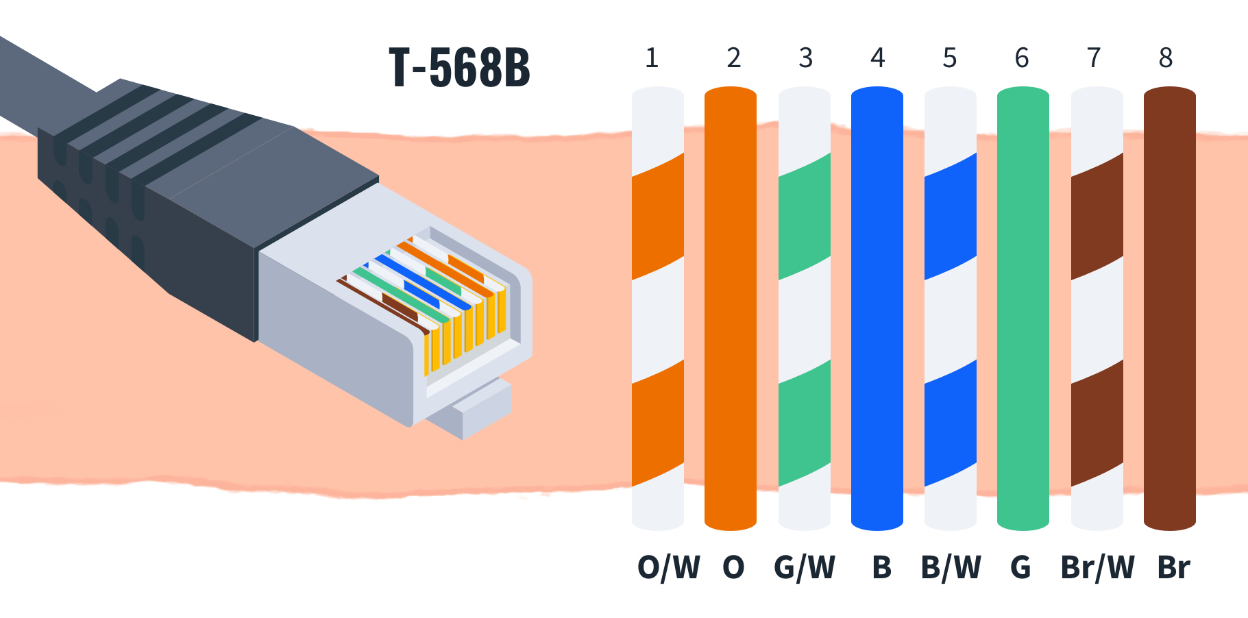
The primary difference between the two standards is the swapping of the green and orange wire pairs. In T568A, the green pair is on pins 1 and 2, and the orange pair is on pins 3 and 6. In T568B, these positions are reversed.
- T568B: This is the most common standard used in North America and general commercial cabling installations. Many professionals default to T568B for all new projects.
- T568A: This standard is more common in residential installations in certain regions and is often required in government or military projects due to historical compliance standards.
Pinout Color Sequences
To wire an RJ45 connector, you must strip the outer jacket of the cable, untwist the internal pairs, and arrange them side-by-side according to the chosen standard. Looking at the connector with the gold pins facing you and the clip facing away, the pins are numbered 1 through 8 from left to right.
| Pin Number | T568A Color | T568B Color |
|---|---|---|
| 1 | White/Green | White/Orange |
| 2 | Green | Orange |
| 3 | White/Orange | White/Green |
| 4 | Blue | Blue |
| 5 | White/Blue | White/Blue |
| 6 | Orange | Green |
| 7 | White/Brown | White/Brown |
| 8 | Brown | Brown |
Prerequisites for Proper Termination
Before beginning the physical wiring process, you must ensure you have the correct materials and tools. Using mismatched components can lead to signal degradation or physical failure of the connector.
- Cable Choice: Ensure your cable category (e.g., Cat6) matches your performance needs. Cat6 or Cat6a is recommended for 2026 infrastructure to support higher bandwidth requirements.
- RJ45 Connectors: Use connectors designed for your specific cable type. Solid-core cable requires different connectors than stranded-core cable (the type found in patch cords).
- Stripping Tool: A dedicated cable stripper is safer than a utility knife, as it prevents nicking the delicate copper strands.
- Crimping Tool: A high-quality ratcheting crimper ensures that the metal pins are pushed fully into the wires, creating a secure electrical contact.
- Cable Tester: An essential tool to verify that all eight wires are in the correct position and that there are no shorts or open circuits.
Step-by-Step Termination Procedure
- Strip the Jacket: Remove about 1.5 inches of the outer insulation from the end of the cable using your stripping tool. Be careful not to cut the inner insulation of the colored wires.
- Untwist and Arrange: Untwist the pairs and straighten the wires. Align them according to the color sequence of either T568A or T568B. Hold them firmly between your thumb and forefinger.
- Trim: Use the cutting blade on your crimping tool to trim the wires straight across, leaving about 0.5 inches of exposed wire. This uniform length is critical so that all wires reach the pins simultaneously.
- Insert: Carefully insert the wires into the RJ45 plug. Ensure the jacket of the cable also goes slightly into the connector, as this provides strain relief once crimped.
- Crimp: Insert the connector into the crimping tool and apply firm, even pressure. The tool will push the metal contacts through the insulation of the individual wires and lock the plastic retainer onto the cable jacket.
- Test: Plug both ends of the cable into a continuity tester. A successful test will show all eight pins lighting up in sequence, confirming a correct and reliable connection.
Troubleshooting Common Issues
When a cable fails the continuity test or does not provide a network connection, the error is almost always at the termination points.
- Split Pairs: This occurs when the color sequence is correct at both ends, but the pinout logic is physically crossed. The most common sign of this is a cable that works for low-speed connections but fails to negotiate a Gigabit link.
- Open Circuits: This happens when a wire is not inserted deep enough into the connector, or the crimping tool failed to push a pin down far enough to pierce the wire's insulation.
- Short Circuits: This usually occurs if the metal strands of two wires are touching, or if excess wire stripping has left exposed copper near the base of the connector.
- Intermittent Connectivity: Often caused by a loose connection where the cable jacket was not secured properly within the RJ45 plug's strain relief mechanism.
Selecting the Right Standard for Your Project
In 2026, the best practice is to choose one standard—either T568A or T568B—and stick to it across your entire building or network infrastructure. Consistency is the most important factor. If you are replacing a cable in an existing environment, identify which standard was used previously by looking at the color sequence on an existing wall jack. Matching the existing standard ensures that your new patch cables will behave predictably with the installed infrastructure.
Frequently Asked Questions
Does it matter if I use T568A or T568B? Technically, no. Both provide the same electrical performance for data transmission. The primary importance is maintaining the same standard at both ends of a single cable. If you mix them, you create a crossover cable, which is rarely needed with modern networking equipment.
Can I use Cat5e connectors on Cat6 cable? You should avoid this. Cat6 wires are generally thicker than Cat5e wires. Using a connector not rated for the specific gauge of your cable can result in a poor fit, difficult insertion, and long-term connection failures due to physical movement.
What is a crossover cable and do I need one? A crossover cable swaps the transmit and receive pairs between ends. In the past, they were required to connect two computers directly. Today, nearly all network ports feature Auto-MDIX, which negates the need for specialized crossover cabling.
How long can an Ethernet cable be before it loses signal? The standard limit for an RJ45-terminated copper Ethernet cable is 100 meters (approximately 328 feet). Exceeding this length leads to signal attenuation, where the data packets become corrupted, resulting in significantly slower speeds or total connection loss.
Do I need shielded or unshielded cable? Most home and small office environments use Unshielded Twisted Pair (UTP). Shielded Twisted Pair (STP) is only necessary in environments with high levels of electromagnetic interference, such as areas with heavy industrial machinery or significant fluorescent lighting arrays.
Professional Recommendation
For most residential and small business installations in 2026, adopt the T568B standard for all new cabling projects. Keep a high-quality cable tester on hand, as visual inspection alone is insufficient to verify that all eight internal connections are securely made. When terminating, prioritize a clean cut and ensure the outer jacket is firmly held by the connector's strain relief clip, as this prevents mechanical stress from pulling the individual wires out of contact over time.