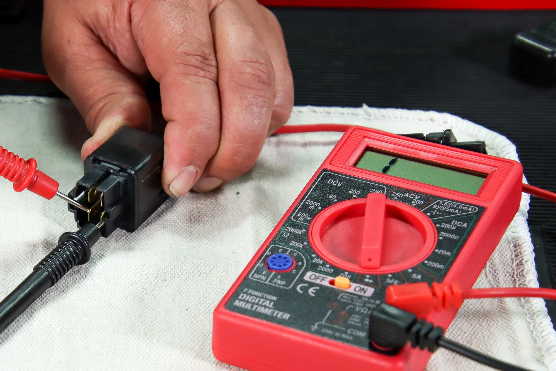
Testing a 3-phase motor with a multimeter involves checking the continuity of the internal windings, measuring the resistance between phases to ensure they are balanced, and verifying that the insulation has not failed by testing for shorts to the ground. These diagnostic steps identify open circuits, shorted turns, and ground faults.
Testing a three-phase motor is a fundamental skill for industrial electricians, HVAC technicians, and maintenance professionals. In 2026, despite the proliferation of smart sensors and predictive maintenance AI, the digital multimeter remains the primary "first-response" tool for diagnosing motor health. Three-phase motors are the workhorses of modern infrastructure, powering everything from industrial conveyors and pumps to large-scale commercial air handling units. When a motor fails to start, trips a circuit breaker, or runs excessively hot, a systematic approach with a multimeter can determine if the motor is salvageable or requires replacement.
Prerequisites and Safety Protocols for 2026
Before attempting any electrical testing, safety must be the absolute priority. Working with three-phase power involves high voltages—typically ranging from 208V to 480V or higher—which can be lethal if handled incorrectly. In 2026, safety standards like NFPA 70E continue to dictate the strict use of Personal Protective Equipment (PPE) and standardized procedures.
Lockout/Tagout (LOTO) Procedures
Never test a motor while it is connected to a live power source unless you are performing a specific live voltage test, which requires advanced training and specialized PPE. For the resistance and continuity tests described in this guide, the motor must be completely de-energized.
- Locate the motor's disconnect switch or circuit breaker.
- Turn the power off and apply a physical lock and a warning tag.
- Verify the absence of voltage: Use your multimeter to check across all three phases (L1-L2, L2-L3, L1-L3) and from each phase to the ground to confirm that no residual voltage remains.
Tool Calibration and Inspection
Ensure your digital multimeter (DMM) is rated for the environment you are working in—typically CAT III 600V or CAT IV for industrial motor leads. Inspect the test leads for cracks or exposed wires. A faulty lead can provide false "Open Line" (OL) readings or, worse, expose the user to a shock hazard.
Step 1: Visual and Mechanical Inspection
Before reaching for the multimeter, a thorough visual inspection can often reveal the problem. Look for signs of overheating, such as charred paint on the motor housing or a distinct "burnt" smell emanating from the terminal box. Check the shaft for physical obstructions. If the bearings have seized, the motor may appear electrically sound but will fail to rotate under load.
Open the motor terminal box and inspect the lead wires. Look for brittle insulation, moisture ingress, or loose connections. In many cases, a "failed" motor is simply a victim of a loose terminal nut or a corroded lug that has increased resistance to the point of failure.
Step 2: Testing Winding Continuity and Resistance
The core of a three-phase motor consists of three separate sets of windings (coils). For the motor to operate correctly, these windings must be intact and balanced.
Understanding the Terminal Layout
Inside the terminal box, you will typically find six leads or three leads, depending on the internal configuration (Wye or Delta). They are usually labeled T1, T2, and T3 (or U, V, and W in European standards). To get an accurate reading of the windings themselves, you should disconnect the motor from the incoming power supply leads. This prevents the multimeter from measuring through the entire building’s electrical system or the Variable Frequency Drive (VFD).
Measuring Phase-to-Phase Resistance
Set your multimeter to the lowest Ohms (Ω) setting. You are looking for very low resistance values, often between 0.5 and 20 ohms, depending on the motor's size and horsepower.
- Test T1 to T2: Place one probe on T1 and the other on T2. Record the resistance.
- Test T2 to T3: Place one probe on T2 and the other on T3. Record the resistance.
- Test T1 to T3: Place one probe on T1 and the other on T3. Record the resistance.
Interpreting Resistance Results
In a healthy 3-phase motor, all three readings should be nearly identical.
- Balanced Readings: If all three measurements are within 3% to 5% of each other, the windings are likely in good condition. For example, if you measure 1.2Ω, 1.2Ω, and 1.3Ω, the motor is electrically balanced.
- Infinite/OL Reading: This indicates an "open" winding. A wire inside the coil has broken or melted, creating a gap. The motor is dead and needs rewinding or replacement.
- Zero Ohms (Short Circuit): If you see 0.00Ω or a significantly lower reading on one phase compared to others, there is a short circuit between the turns of that winding.
- Unbalanced Readings: If you see 1.2Ω, 1.2Ω, and 4.5Ω, the high-resistance phase has likely suffered from heat damage or poor internal connections. This imbalance will cause the motor to vibrate, run hot, and eventually fail.
Step 3: Testing Insulation Resistance to Ground
One of the most common causes of motor failure is insulation breakdown. Over time, the varnish coating on the copper windings degrades due to heat, vibration, or moisture, allowing the electricity to "leak" to the motor's metal frame (the ground). This is called a "ground fault."
Performing the Ground Test
Set your multimeter to the highest possible Ohms (MΩ or Mega-ohms) setting.
- Attach one probe to a clean, unpainted spot on the motor’s metal frame or the ground screw.
- Touch the other probe to each of the motor leads (T1, T2, and T3) one at a time.
- Reading T1 to Ground.
- Reading T2 to Ground.
- Reading T3 to Ground.
Interpreting Insulation Results
- OL (Open Line): This is the desired result for a standard multimeter test. It means the resistance is higher than the meter can measure (effectively infinity), indicating no path to ground.
- Any Numerical Value: If your multimeter shows a reading (e.g., 20kΩ or 2MΩ), the insulation is failing. While a reading in the millions of ohms (MΩ) might seem high, any continuity between the windings and the frame is a sign of impending failure.
- 0.00Ω: This indicates a "dead short" to ground. The winding is physically touching the motor casing. This will trip a circuit breaker or blow a fuse immediately upon startup.
Note: While a multimeter is excellent for identifying dead shorts, it uses a very low voltage (usually 9V) to test resistance. In 2026, professional standards recommend following up with an Insulation Resistance Tester (Megohmmeter), which applies 500V or 1000V to detect insulation weaknesses that a standard multimeter might miss.
Step 4: Testing for Phase-to-Phase Shorts
Occasionally, two separate windings can short to each other. This is different from a winding shorting to the frame.
- Ensure all six leads are disconnected from each other if the motor is a 6-lead or 9-lead configuration.
- Test resistance between Winding 1 and Winding 2.
- The multimeter should read OL (infinite resistance).
- If there is any continuity between different winding sets that are supposed to be isolated, the motor has an internal phase-to-phase short.
Troubleshooting Summary Table
The following table outlines common multimeter readings and what they signify for 3-phase motor health.
| Test Connection | Multimeter Reading | Potential Diagnosis |
|---|---|---|
| T1-T2, T2-T3, T1-T3 | Identical Low Ohms | Windings are balanced and healthy. |
| T1-T2, T2-T3, T1-T3 | One reading is significantly higher | High resistance in one coil; indicates damage. |
| Any Phase Pair | "OL" (Infinite) | Open circuit (broken internal wire). |
| Any Phase Pair | 0.00 Ohms (or near zero) | Short circuit between winding turns. |
| Any Phase to Frame | Any numerical reading | Insulation breakdown (leakage to ground). |
| Any Phase to Frame | 0.00 Ohms | Dead short to ground; immediate failure. |
| Any Phase to Frame | "OL" (on MΩ setting) | Good insulation integrity. |
Why Motors Fail: The Technical Context for 2026
Understanding why your multimeter is showing certain readings can help prevent future failures. In 2026, several factors remain the primary culprits for motor degradation:
- Thermal Overload: Continuous operation above the rated temperature causes the winding insulation to become brittle. For every 10°C increase above the rated temperature, the insulation life is effectively halved.
- VFD Harmonics: Variable Frequency Drives are essential for efficiency, but they can induce "shaft voltages" and high-frequency harmonics that stress insulation and erode bearings.
- Contamination: Dust, oil, and moisture can enter the terminal box or the motor housing, creating a conductive path that leads to ground faults.
- Voltage Imbalance: If the incoming supply voltage is unbalanced (e.g., L1-L2 is 480V but L2-L3 is 460V), the motor will draw excessive current on the lower voltage phase, leading to the winding damage you detect during a resistance test.
Practical FAQ
1. Can I test a 3-phase motor with a multimeter while it's energized?
No, you cannot perform resistance or continuity tests on a live motor. Attempting to measure Ohms on a live circuit will likely damage your multimeter and poses a severe risk of arc flash or electrocution. If you need to check a running motor, you must use a clamp-on ammeter to check the current draw on each phase or a voltmeter to check the incoming supply voltage.
2. What is a "normal" resistance reading for a 3-phase motor?
There is no single "normal" number because resistance depends on the motor's size. A small 1HP motor might have a resistance of 10-15 ohms, while a large 100HP motor might have a resistance of less than 0.1 ohms. The key is balance. All three phases should be within 5% of each other. If you are unsure, consult the manufacturer’s technical datasheet for the specific winding resistance.
3. What does "OL" mean on my multimeter during a motor test?
"OL" stands for "Open Line" or "Over Limit." If you see this when testing between two phases (e.g., T1 to T2), it means the winding is broken (an open circuit). If you see "OL" when testing between a phase and the motor frame, it is a good sign, indicating that the insulation is intact and there is no path to ground.
4. Is a multimeter enough to declare a motor "good"?
A multimeter is excellent for finding "dead" motors (open windings or hard shorts). However, it cannot always find "dying" motors. Insulation can be weak enough to fail at 480V but still show "OL" on a 9V multimeter test. In industrial settings, a Megger (insulation tester) and a vibration analysis tool are used alongside the multimeter for a complete health profile.
5. Do I need to disconnect the motor from the VFD before testing?
Yes. It is critical to disconnect the motor leads from the Variable Frequency Drive (VFD) or soft starter before performing resistance or insulation tests. The testing voltage from the multimeter—or especially the high voltage from a Megger—can damage the sensitive power electronics (IGBTs) inside the drive.
Final Recommendation
When testing a 3-phase motor, always start with the Ground Test. A ground fault is the most common reason for a motor to trip a breaker immediately. If the motor is not grounded, proceed to the Phase-to-Phase Resistance Test to ensure the windings are balanced. If your multimeter shows a variance of more than 5% between phases or any "OL" readings between windings, the motor should be pulled from service. For critical applications, always supplement your multimeter findings with a specialized insulation tester to ensure the motor can handle its full operating voltage under load.