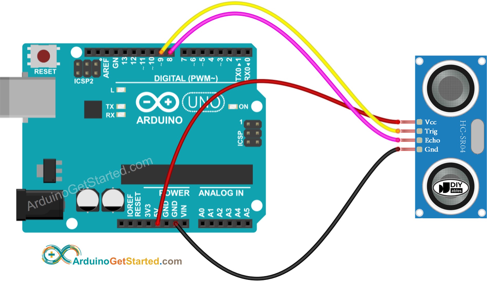
The HC-SR04 ultrasonic sensor measures distance by emitting high-frequency sound waves and calculating the time it takes for the echo to bounce back to the receiver. Integrating this sensor with an Arduino board requires a few simple physical connections and a short program to translate sound travel time into a readable distance in centimeters or inches.
Introduction to the HC-SR04 Ultrasonic Sensor and Arduino
Distance measurement is a fundamental requirement in robotics, automation, and interactive electronics. Whether you are building an obstacle-avoiding robot, a liquid level monitor, or a parking assistance system, knowing how to measure distance accurately without physical contact is invaluable. The HC-SR04 ultrasonic distance sensor is one of the most popular, cost-effective, and reliable components available for makers, students, and professional engineers alike.
Operating on the principle of echolocation, much like bats navigate, the HC-SR04 sends out a short acoustic burst and waits for it to reflect off a nearby surface. When paired with an Arduino microcontroller, this hardware combination transforms sound waves into precise digital logic. This comprehensive, step-by-step guide walks you through every phase of the integration process—from understanding technical specifications and wiring your circuit to writing the code, calibrating the sensor, and troubleshooting common real-world errors.
Understanding How the HC-SR04 Works
Before wiring your hardware, it helps to understand the underlying physics and electronics of the HC-SR04 module. The sensor consists of two main ultrasonic transducers—one acts as a transmitter that converts electrical signals into 40 kHz sound waves, and the other acts as a receiver that converts returning sound waves back into electrical signals.
The module operates on a 5-volt direct current (DC) supply and draws a very low operating current, typically around 15 milliamps. It features four primary pins: VCC, Trig (Trigger), Echo, and GND (Ground). When the Arduino sends a high-level signal lasting at least 10 microseconds to the Trig pin, the module automatically transmits an 8-cycle burst of ultrasound at 40 kHz.
As the sound waves travel through the air, the Echo pin goes high. The moment the receiver detects the returning echo, the Echo pin drops back to low. By measuring the total duration that the Echo pin remains high using the Arduino pulseIn() function, you can calculate the distance to the target object. Because sound travels through dry air at approximately 343 meters per second (or 0.0343 centimeters per microsecond), the mathematical formula divides the total round-trip time by two and multiplies it by the speed of sound.
Gather Your Prerequisites and Hardware Components
Successful electronics projects begin with proper preparation. Before diving into the wiring and coding stages, verify that you have all the necessary physical components assembled on your workbench.
- An Arduino board (such as the Arduino Uno, Nano, or Mega)
- An HC-SR04 ultrasonic sensor module
- A breadboard for prototyping circuits
- A set of male-to-male and male-to-female jumper wires
- A USB cable to connect your Arduino to a computer
- The Arduino IDE (Integrated Development Environment) installed on your computer
Ensure your workspace is clean, well-lit, and free from static electricity risks. Having a breadboard simplifies the circuit layout and prevents accidental short circuits that can damage your microcontroller or sensor module.
Step 1: Inspect the HC-SR04 Pinout and Specifications
The first practical step is familiarizing yourself with the physical layout and pin designations of the HC-SR04 module. Looking at the front of the sensor, you will see two silver cylindrical metal containers, which are the transmitter and receiver capsules.
On the back or bottom of the printed circuit board, the four connection pins are clearly labeled. It is vital to connect these pins to the correct voltage levels and digital inputs on your Arduino to prevent permanent hardware failure.
| Pin Name | Description | Arduino Connection |
|---|---|---|
| VCC | Power Supply Input | 5V Pin |
| Trig | Trigger Input for Sound Burst | Digital Pin (e.g., Pin 9) |
| Echo | Echo Output for Return Signal | Digital Pin (e.g., Pin 10) |
| GND | Ground Reference | GND Pin |
Never connect the VCC pin of the HC-SR04 to a 3.3V source if you expect reliable 4-meter range performance, as the internal circuitry is optimized for a stable 5-volt supply. Furthermore, take care not to bend the pins or apply excessive mechanical force to the transducer cylinders, as their internal piezoelectric crystals are fragile.
Step 2: Set Up the Physical Circuit Connections
With your pinout knowledge established, you can now connect the HC-SR04 sensor to your Arduino board. For safety, ensure your Arduino is unplugged from your computer or power supply while assembling the circuit.
- Place the HC-SR04 sensor onto your breadboard, spanning the center divider so that its four pins occupy separate electrical rows.
- Connect a jumper wire from the VCC pin of the sensor to the 5V output pin on your Arduino.
- Connect a jumper wire from the GND pin of the sensor to a GND pin on your Arduino.
- Connect a male-to-male jumper wire from the Trig pin of the sensor to Digital Pin 9 on your Arduino.
- Connect a male-to-male jumper wire from the Echo pin of the sensor to Digital Pin 10 on your Arduino.
Double-check every connection against your schematic layout. Reversing the VCC and GND connections can cause the sensor to overheat rapidly and destroy the onboard integrated circuits.
Step 3: Configure the Arduino IDE Environment
With the hardware securely assembled, turn your attention to the software side of the project. Open the Arduino IDE on your computer and ensure your development environment is properly configured to communicate with your hardware.
- Plug your Arduino board into your computer using the appropriate USB cable.
- Navigate to the Tools menu in the top toolbar of the Arduino IDE.
- Select Board and choose the specific model of Arduino you are using (such as "Arduino Uno").
- Select Port and choose the serial port corresponding to your connected Arduino board. If the port option is greyed out, check your USB cable or reinstall your USB-to-serial drivers.
No external libraries are strictly required to operate the HC-SR04 sensor, as the native Arduino programming language provides all the necessary timing and digital I/O functions. This keeps your sketch lightweight and easy to modify.
Step 4: Write the Trigger and Echo Control Code
Writing the sketch requires configuring your digital pins and utilizing the digitalWrite() and pulseIn() functions. Create a new sketch in the Arduino IDE and paste the foundational structure for pin initialization.
const int trigPin = 9; const int echoPin = 10; void setup() { pinMode(trigPin, OUTPUT); pinMode(echoPin, INPUT); Serial.begin(9600); } void loop() { // Clearing the trigPin condition digitalWrite(trigPin, LOW); delayMicroseconds(2); // Setting the trigPin HIGH for 10 microseconds digitalWrite(trigPin, HIGH); delayMicroseconds(10); digitalWrite(trigPin, LOW); // Reading the echoPin and returning the sound wave travel time in microseconds long duration = pulseIn(echoPin, HIGH); // Calculating the distance int distance = duration * 0.034 / 2; Serial.print("Distance: "); Serial.print(distance); Serial.println(" cm"); delay(500); }
In this script, the loop() function first clears the trigger pin by setting it low for two microseconds. It then generates a 10-microsecond high pulse, which commands the sensor to emit its ultrasonic burst. The pulseIn() function waits for the echo pin to go high, starts a timer, waits for it to go low, and returns the elapsed time in microseconds.
Step 5: Calculate Distance and Convert Units
The raw value returned by pulseIn() represents the total round-trip time of the sound wave in microseconds. To convert this time measurement into a meaningful physical distance, apply the speed of sound constant.
The speed of sound in dry air is approximately 0.034 centimeters per microsecond. Because the sound wave travels outward to the object and then bounces back to the receiver, the total distance traveled is double the distance between the sensor and the object. Therefore, the formula multiplies the duration by 0.034 and divides the result by two:
$$\text{Distance (cm)} = \frac{\text{Duration} \times 0.0343}{2}$$
If you prefer working in imperial units rather than metric units, you can convert centimeters into inches by dividing the centimeter result by 2.54, or by multiplying the duration by the speed of sound in inches per microsecond (approximately 0.0133 inches per microsecond) and dividing by two.
Step 6: Upload and Test Your Project
With your code written and verified, it is time to upload the sketch to your microcontroller and verify its real-world performance.
- Click the Verify (checkmark) button in the top-left corner of the Arduino IDE to compile your code and check for syntax errors.
- Click the Upload (right-arrow) button to transfer the compiled binary file to your Arduino board.
- Once the upload finishes successfully, open the Serial Monitor by clicking the magnifying glass icon in the top-right corner of the IDE window.
- Ensure the baud rate dropdown in the Serial Monitor is set to match your code (
9600 baud).
Move your hand or an object back and forth in front of the ultrasonic sensor, keeping it within a range of 2 centimeters to 400 centimeters. You should see the distance values update in real time on the Serial Monitor screen.
Step 7: Analyze Operational Limitations and Edge Cases
While the HC-SR04 is remarkably versatile, it has distinct physical and environmental limitations that every developer must account for. Understanding these constraints prevents frustrating troubleshooting sessions later in your project lifecycle.
- Beam Angle: The HC-SR04 has an effective acoustic beam angle of approximately 15 degrees. Objects located outside this cone may fail to reflect enough sound energy back to the receiver.
- Target Material and Surface Shape: Soft, sound-absorbing materials (such as foam, fabric, or heavy carpets) absorb ultrasonic waves rather than reflecting them, leading to inaccurate readings or complete detection failure. Similarly, spherical or sharply angled objects deflect sound waves away from the receiver.
- Range Boundaries: The reliable working range of the standard HC-SR04 spans from 2 centimeters to 400 centimeters. Objects closer than 2 cm produce erratic readings, while distances beyond 400 cm suffer from signal attenuation and background noise interference.
- Environmental Factors: Variations in ambient temperature and humidity alter the speed of sound in air. For high-precision scientific applications, developers must incorporate temperature compensation sensors, such as the DHT11 or DHT22, into their calculations.
Step 8: Implement Best Practices for Stable Readings
Raw sensor data often exhibits minor jitter or fluctuation due to electrical noise, minor air currents, or surface irregularities. Implementing software-level filtering significantly improves the stability of your distance measurements.
Instead of relying on a single instantaneous reading, calculate a rolling average over multiple consecutive samples. For example, you can collect five readings in quick succession, discard any statistical outliers, and compute the arithmetic mean before triggering downstream actions like motor control or display updates.
int getSmoothedDistance() { int total = 0; int samples = 5; for (int i = 0; i < samples; i++) { digitalWrite(trigPin, LOW); delayMicroseconds(2); digitalWrite(trigPin, HIGH); delayMicroseconds(10); digitalWrite(trigPin, LOW); long duration = pulseIn(echoPin, HIGH); total += duration * 0.034 / 2; delay(10); } return total / samples; }
Adding a short hardware decoupling capacitor (such as a 100µF electrolytic capacitor across the VCC and GND pins near the sensor) also helps stabilize power delivery and reduces electrical interference from switching motors or wireless modules sharing the same power rail.
Step 9: Troubleshoot Common Hardware and Code Issues
Even experienced makers occasionally encounter setup hurdles when working with ultrasonic sensors. Review this troubleshooting checklist if your sensor fails to respond as expected:
- Constant Zero Readings: If the Serial Monitor displays a constant distance of 0 cm, check your Echo pin wiring. A loose connection or incorrect pin assignment in your code will prevent the Arduino from detecting the return pulse.
- Unresponsive or Frozen Program: The
pulseIn()function blocks program execution while waiting for an incoming pulse. If no echo returns—for instance, when an object is placed beyond 4.5 meters—the program freezes for one full second before timing out. To prevent this, configure a timeout parameter in your function call, such aspulseIn(echoPin, HIGH, 30000);, which limits the wait time to 30 milliseconds. - Erratic Jump Values: If your distance readings fluctuate wildly while the target object is completely stationary, check your power supply. Running an HC-SR04 off an unstable USB bus or sharing power with noisy DC servo motors causes voltage sags that disrupt sensor timing. Power your peripherals from a dedicated external regulated supply sharing a common ground with the Arduino.
Step 10: Explore Advanced Next Actions and Projects
Once you have mastered basic distance measurement with the HC-SR04 and Arduino, you can scale your project to solve complex real-world challenges. Consider incorporating your sensor into one of the following intermediate or advanced applications:
- Autonomous Obstacle-Avoiding Robot: Mount the HC-SR04 onto a micro servo motor (such as a standard SG90) to create a scanning radar system that allows a wheeled robot to map its environment and steer around barriers in real time.
- Digital Tape Measure with LCD Display: Interface an I2C-enabled 16x2 Liquid Crystal Display (LCD) to your Arduino, turning your sensor setup into a portable, handheld electronic distance meter.
- Automated Parking Assistant: Program RGB LEDs or an active piezoelectric buzzer to change tone and color intensity as an approaching vehicle gets closer to a garage wall, replicating modern automotive safety features.
By combining robust wiring practices, clean filtering code, and a solid understanding of acoustic physics, you can leverage the HC-SR04 sensor to build reliable, high-precision distance-sensing systems for any maker project.