The 3D Print Toolbox is a built-in Blender add-on that analyzes and cleans up 3D meshes to ensure they are structurally sound, watertight, and optimized for physical fabrication, saving hours of troubleshooting before exporting to slicer software.
Introduction to the 3D Print Toolbox in Blender
Preparing digital assets for physical fabrication requires a distinct set of geometric standards compared to video game development, visual effects, or architectural rendering. While a digital model only needs to look convincing from a camera's perspective, a physical 3D print requires a mathematically solid, airtight enclosure with zero thickness or non-manifold geometry. Without these structural guarantees, slicing software will fail to interpret where the solid material begins and ends, leading to catastrophic print failures, missing faces, or corrupted G-code.
Blender has long been celebrated as a versatile, powerful modeling suite, but its native focus on artistic freedom and non-destructive workflows can inadvertently introduce geometric anomalies. Intersecting geometry, inverted normals, floating vertices, and zero-area faces are common when sculpting or boolean modeling. To bridge the gap between digital art and physical manufacturing, the developers of Blender integrated a specialized utility known as the 3D Print Toolbox add-on.
This built-in feature acts as an automated pre-flight checker and repair suite. Rather than forcing users to manually inspect thousands of vertices across a complex mesh, the 3D Print Toolbox automates mesh evaluation, highlights critical errors in real-time, and provides one-click cleanup routines. Understanding how to activate, configure, and utilize this tool is essential for anyone transitioning from digital sculpting and modeling to desktop or industrial additive manufacturing.
Accessing and Enabling the Add-On
Unlike many third-party utilities that require downloading external repositories, compiling source code, or placing scripts into specific directories, the 3D Print Toolbox is shipped directly with official Blender installations. However, because Blender keeps its workspace clean by default and only loads core modeling features out of the box, specialized utilities like the 3D Print Toolbox must be manually enabled within the preferences menu.
To activate the tool, open Blender and navigate to the top-left corner of the interface. Select Edit, then click on Preferences to open the Blender Preferences window. From there, select the Add-ons tab on the left-hand side. In the search bar at the top right of the add-ons panel, type 3D Print.
The search filter will instantly isolate the entry labeled Mesh: 3D Print Toolbox. Click the small checkbox next to the entry to enable it. Once checked, the add-on is integrated into Blender’s interface workspace. You can now close the preferences window.
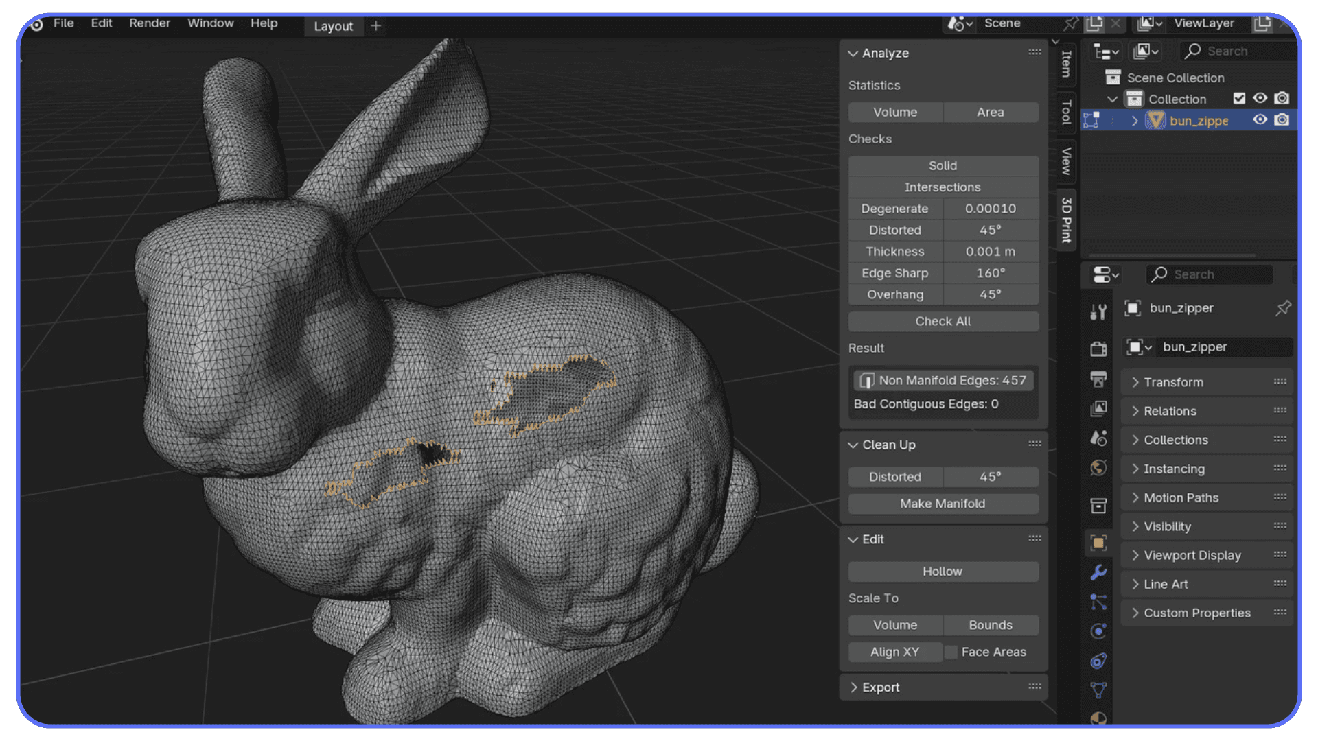
To access the newly enabled tools, return to your 3D viewport, ensure you are in Object Mode or Edit Mode, and press the N key on your keyboard to toggle the sidebar (the N-panel) on the right side of the screen. Scroll down the list of tabs until you locate the one labeled 3D Print. Clicking this tab reveals the control panel, divided into intuitive sections covering mesh analysis, cleanup operations, export settings, and scaling parameters.
Analyzing Geometry: Understanding Mesh Errors
Before executing any automated repairs, it is vital to understand the types of geometric failures that cause 3D prints to fail. The Analyze section of the 3D Print Toolbox scans your active mesh against the physical requirements of additive manufacturing and reports specific error counts. Clicking any of the analysis buttons will evaluate the geometry and highlight problem areas directly on your model in the viewport.
| Error Type | Description | Impact on 3D Printing |
|---|---|---|
| Non-Manifold | Edges shared by more than two faces, or open boundaries in a mesh. | Slicers cannot determine inside from outside; leads to hollow or corrupted prints. |
| Intersecting Faces | Faces that pass through one another within the interior of the mesh. | Creates internal geometry confusion, slicing artifacts, and wasted filament/resin. |
| Degenerate Faces | Faces with zero area (collapsed edges or points sharing a single line). | Adds unnecessary file bloat and causes calculation errors in slicer engines. |
| Overhanging Faces | Faces exceeding safe bridging or support angles (e.g., >45 degrees). | Causes sagging, drooping, or total structural collapse during printing without supports. |
Interpreting Non-Manifold Geometry
A manifold mesh is essentially a continuous surface that completely encloses a volume without any holes, gaps, or internal walls. In the physical world, a solid object cannot have a hole in its skin unless it opens to the outside environment. When the 3D Print Toolbox reports Non-Manifold edges, it means the mesh has open boundaries (like a ripped piece of paper) or internal structural partitions that violate the rules of a solid volume. Identifying these allows you to target specific areas using Blender's Edit Mode vertex and edge selection tools.
Checking Dimensions and Scale
Beyond structural integrity, the analysis panel allows you to check the physical dimensions of your model. New users frequently model objects without paying attention to real-world scale, exporting a file that Blender interprets as one meter wide, but which a slicer interprets as one millimeter wide. Using the dimension checks within the toolbox ensures your model conforms to the build volume limits of your specific printer before you proceed to export.
Automated Cleanup and Repair Operations
Once the analysis phase reveals the structural shortcomings of your model, the Clean Up section of the 3D Print Toolbox provides automated routines to rectify these issues. While manual retopology and mesh editing remain the gold standard for flawless optimization, the toolbox's automated tools can resolve minor errors in seconds.
The Make Manifold Operator
The most powerful automated feature in the suite is the Make Manifold operator. When clicked, Blender attempts to automatically bridge open boundary loops, delete stray vertices, and stitch minor tears in the mesh topology.
However, users must exercise caution: automated algorithms do not possess semantic understanding of what the model should look like. For simple objects, Make Manifold works flawlessly. For complex organic models or intricate character sculpts, automated stitching can sometimes distort facial features, close intended openings (such as the mouth or eye sockets of a character), or create undesirable internal geometry. Always inspect your model in Edit Mode after running an automated cleanup.
Handling Degenerate Geometry and Loose Parts
The cleanup suite also features dedicated operators for removing degenerate geometry and isolated artifacts. Degenerate cleanup isolates and deletes zero-area faces and zero-length edges that accumulate during boolean operations or aggressive sculpting. Similarly, the cleanup routine can isolate Loose parts—stray vertices, floating polygons, or internal support structures left behind from previous modeling steps—and delete them instantly, keeping your mesh clean and reducing file size.
Exporting and Unit Management
After analyzing and repairing your mesh, the final step in the preparation workflow is exporting the file into a format compatible with slicing software, such as STL, OBJ, or PLY. The 3D Print Toolbox streamlines this process by providing dedicated export buttons at the bottom of the panel, complete with unit scaling options.
Choosing the Correct File Formats
- STL (Standard Triangle Language): The universal standard for 3D printing. It represents surfaces as a collection of triangles. While ubiquitous, it does not store color, material, or unit scale data.
- OBJ (Wavefront): A widely supported format that retains material and color data if texture maps are exported alongside the geometry.
- 3MF (3D Manufacturing Format): A modern, XML-based alternative to STL that supports color, multiple materials, and precise unit scaling within a single compressed archive.
Managing Scale and Unit Conversion
One of the most frequent causes of printing scale errors is the mismatch between Blender's abstract unit system and the millimeter-based measurement standard used by slicers like Cura, PrusaSlicer, or OrcaSlicer. Blender units can represent meters, centimeters, or arbitrary units depending on scene settings.
The 3D Print Toolbox export panel allows you to explicitly define export parameters, ensuring that a cube measuring 20 units in Blender exports precisely as 20 millimeters in your slicer. Always verify your printer profile's unit scale settings against the export parameters in this panel to avoid scaling disasters on the build plate.
Advanced Troubleshooting and Common Pitfalls
Even with the assistance of the 3D Print Toolbox, certain complex models will persistently throw errors or fail to slice correctly. Recognizing why these failures occur helps you adjust your modeling habits and resolve persistent issues manually.
Boolean Operations and Internal Geometry
Many hard-surface models are created using Boolean modifiers (Union, Difference, Intersect). While powerful, Booleans frequently leave behind floating internal faces, non-manifold edges, and overlapping vertex clusters that the automated 3D Print Toolbox cleanup cannot resolve without altering the external silhouette. If Make Manifold fails to fix a model, switch to Edit Mode (Tab), press Alt + M or M to merge vertices by distance, and manually inspect the interior cavities using wireframe display mode (Z).
Normal Orientation
Inverted face normals are another invisible trap for 3D printing. A face normal points outward to indicate which side is the exterior of the model. If a normal is flipped inward, the slicer interprets it as a hole or an inverted surface. While the 3D Print Toolbox helps identify manifold errors, you can check normals manually in Edit Mode by opening the Viewport Overlays menu (the overlapping circles icon in the top right of the viewport) and checking the box for Face Orientation. Blue faces indicate correct outward orientation, while red faces indicate inverted normals that must be recalculated using Shift + N.
Frequently Asked Questions
Is the 3D Print Toolbox add-on free?
Yes, the 3D Print Toolbox is completely free and comes pre-installed with every official version of Blender. You do not need to download external files or pay for a license; you only need to activate it within the Blender preferences menu.
Why does the add-on report non-manifold errors on a simple cube?
Even a basic cube can become non-manifold if its scale is unapplied, if it contains duplicate vertices overlapping in space, or if faces have been deleted. To fix this, select the cube in Object Mode, press Ctrl + A, and choose All Transforms to reset its scale data, then run the cleanup operator.
Can the 3D Print Toolbox automatically fix thin walls?
No. While the tool can detect non-manifold geometry, intersecting faces, and holes, it cannot dynamically thicken walls that fall below your 3D printer's nozzle or laser diameter. Wall thickness adjustments must be made manually using the Solidify modifier or direct modeling in Edit Mode.
Does the add-on support color 3D printing formats like VRML or 3MF?
The 3D Print Toolbox primarily focuses on geometric mesh analysis, repair, and export. While you can export to formats like 3MF and OBJ that support color data, texturing, vertex colors, and multi-material assignments must be handled through Blender's material and shading nodes prior to export.
What should I do if the automated repair ruins my model's details?
Automated algorithms evaluate topology mathematically without regard for artistic intent. If Make Manifold or automated cleanup alters critical features, undo the action (Ctrl + Z), switch to Edit Mode, and fix the specific problem areas manually using vertex snapping, bridge edge loops, and normal recalculation.
Next Actions and Best Practices
To integrate the 3D Print Toolbox smoothly into your daily 3D printing workflow, establish a standardized pre-flight checklist. Always apply your object transforms (Ctrl + A) before modeling concludes, run the Analyze suite as a standard habit before exporting, and inspect highlighted error zones in Edit Mode rather than relying exclusively on blind automated fixes. By combining Blender's artistic flexibility with the rigorous diagnostic capabilities of the 3D Print Toolbox, you can eliminate guesswork and ensure your digital designs translate flawlessly into physical objects.