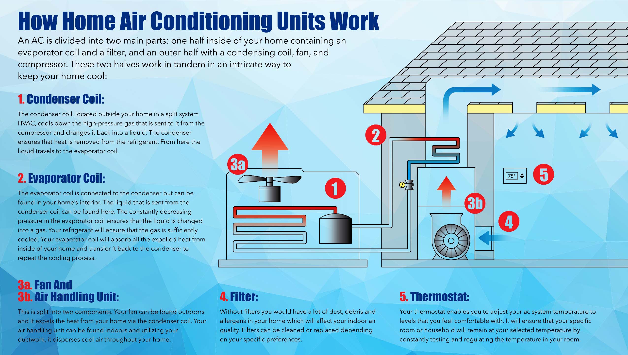
An air conditioner airflow diagram maps the precise paths that indoor and outdoor air travel through your cooling system, illustrating how warm air is drawn from living spaces, passed over freezing evaporator coils to extract heat and moisture, and then blown back as conditioned air through supply ducts.
Introduction to Air Conditioner Airflow
When homeowners look at an air conditioner airflow diagram, they are often trying to solve a common comfort problem, such as weak airflow from specific vents, rooms that never quite cool down, or unexpectedly high utility bills. At its core, a residential air conditioner is not merely a cooling machine; it is fundamentally a forced-air distribution system. It relies on a continuous, balanced cycle of air movement to transfer thermal energy from inside your home to the outdoors. Without a clear understanding of this pathway, diagnosing routine maintenance issues or recognizing the early warning signs of component failure becomes an exercise in guesswork.
To fully grasp how an air conditioner functions, you must look beyond the mechanical hum and icy grates to visualize the invisible currents of air moving through your walls, ceilings, and mechanical closets. This guide breaks down the anatomy of an air conditioner airflow diagram, detailing every component, identifying common bottlenecks, and explaining the thermodynamics of forced-air cooling.
The Core Components of an Air Conditioning Airflow System
An air conditioning system is divided into two primary environments: the indoor unit (handling air handlers, furnaces, or fan coil units) and the outdoor unit (housing the compressor and condenser coil). An airflow diagram primarily focuses on the indoor side, where air is pulled, filtered, chilled, and redistributed.
- Return Air Vents
- Filter
- Blower Fan
- Evaporator Coil
- Supply Plenum
- Supply Vents
Return Air Grilles and Ducts
The process begins at the return air grilles. These are typically large, louvered vents mounted on walls or ceilings in central locations throughout a home. The return side operates under low pressure, acting as a vacuum that pulls stale indoor air out of rooms. This air travels through large-diameter return ducts back to the central mechanical unit.
The Air Filter
Positioned immediately before the air handler or furnace blower, the air filter is a critical checkpoint on the airflow diagram. Its primary purpose is protecting the sensitive mechanical components—specifically the blower motor and the evaporator coil—from dust, pet hair, and debris. As air passes through the filter at high velocities, particulate matter is trapped in the media. A clogged filter introduces massive static pressure, choking the airflow diagram right at the entry point and reducing overall system efficiency.
Blower Motor and Fan Assembly
Often referred to as the heart of the airflow system, the blower fan creates the pressure differential required to move air through the entire network. Modern systems use either standard multi-speed Permanent Split Capacitor (PSC) motors or high-efficiency Electronically Commutated Motors (ECM). An ECM motor dynamically adjusts its speed to maintain consistent cubic feet per minute (CFM) delivery, even as static pressure fluctuates due to dirty filters or closed dampers.
Evaporator Coil
Once pressurized by the blower fan, the air is forced directly across the evaporator coil. This A-shaped or slanted metal coil is filled with cold, low-pressure liquid refrigerant supplied by the outdoor condensing unit. As the warm indoor air sweeps across the freezing fins of the evaporator coil, thermal energy transfers from the air into the refrigerant. This process cools the air and causes ambient humidity to condense into liquid water, which drips into a condensate pan and drains away.
Supply Plenum and Ductwork
After shedding its heat and moisture at the evaporator coil, the air enters the supply plenum—a sheet metal box that acts as a distribution manifold. From the plenum, the air branches out into rigid or flexible supply ducts. These ducts taper as they travel further from the main trunk line, maintaining consistent air velocity until the conditioned air exits through supply registers into individual rooms.
The Step-by-Step Airflow Cycle
Understanding the sequence of operations helps technicians and homeowners isolate where airflow breaks down. The journey of a single cubic foot of air follows a strict, continuous thermodynamic loop.
- Intake and Collection: Warm air from living spaces is drawn into return grilles by the suction side of the blower fan.
- Filtration: The air passes through the filter medium, removing suspended particulate matter before it can coat the delicate metal fins of the coil.
- Mechanical Propulsion: The blower fan forces the filtered air upward or outward into the evaporator compartment, creating positive pressure.
- Heat Exchange and Dehumidification: The air sweeps across the cold evaporator coil. Heat is absorbed by the refrigerant, and moisture condenses out of the air stream.
- Redistribution: The chilled, dehumidified air collects in the supply plenum and travels through the duct network.
- Room Delivery: Air discharges through supply registers, sweeping across living spaces to displace warmer air, which eventually finds its way back to the return grilles.
Comparing Airflow Systems: Standard vs. Variable-Speed
Not all airflow diagrams behave the same way. The type of blower motor installed in your air handler fundamentally changes how air moves through your home.
| Feature / Metric | Single-Stage (Fixed Speed) | Two-Stage (Variable Speed / ECM) |
|---|---|---|
| Blower Operation | On or Off (100% capacity) | Operates at multiple speeds (low, medium, high) |
| Airflow Consistency | Can create pressure spikes and drafts | Maintains steady, continuous CFM delivery |
| Humidity Control | Moderate; can leave air clammy | Excellent; longer run times pull more moisture |
| Energy Efficiency | Lower; consumes high wattage on startup | Higher; uses minimal power on low speeds |
| Noise Levels | Louder due to sudden air rushes | Quieter due to ramp-up and ramp-down design |
Diagnosing Airflow Issues Using the Diagram
When an airflow diagram is interrupted, system performance plummets. Recognizing where restrictions occur can save you from costly emergency service calls.
Low Airflow at Registers
If certain rooms feel stuffy while others are cold, look at the supply side of the diagram. Common culprits include partially closed manual duct dampers, crushed flexible ductwork in the attic or crawlspace, or an improperly balanced duct system where runs are too long or too narrow.
Weak Return Pull
If you hold a piece of tissue paper up to a return grille and it barely flutters, the return side is starved. This is almost always caused by a severely blocked air filter, blocked return grilles covered by furniture or rugs, or an undersized return duct configuration that cannot keep pace with the blower fan's capacity.
Coil Freezing Despite Good Fan Operation
If the blower is running and registers have air, but the air coming out is warm or the outdoor refrigerant line is coated in ice, the issue lies in the heat exchange phase. Insufficient airflow across the evaporator coil (often due to dirty coil fins or a collapsed duct) prevents the refrigerant from absorbing enough heat, causing the coil temperature to drop below freezing and turning condensation into solid ice.
Frequently Asked Questions
What is the most common cause of restricted airflow in an air conditioner?
A dirty, neglected air filter is by far the most frequent culprit. When dust and debris blanket the filter media, it chokes the system's intake, drastically lowering the volume of air passing over the evaporator coil and reducing overall cooling capacity.
How does duct design affect an air conditioner airflow diagram?
Ductwork acts as the highway for your conditioned air. If ducts are too small, contain sharp ninety-degree turns, or suffer from leaks and disconnections, static pressure rises. High static pressure forces the blower motor to work harder, lowering CFM output and driving up electricity usage.
Why do some rooms get less airflow than others?
Rooms located at the farthest ends of the duct run naturally experience pressure drops. Additionally, poorly balanced damper valves, blocked supply registers, or duct leaks in unconditioned spaces like attics can divert air before it ever reaches your living areas.
Can a ceiling fan change the airflow dynamics of an AC system?
Ceiling fans do not alter the central AC airflow diagram or lower ambient room temperatures. Instead, they create a wind-chill effect on human skin by evaporating moisture. Turning on ceiling fans allows you to raise your thermostat setting by a few degrees without sacrificing personal comfort.
Conclusion and Next Actions
Mastering the mechanics shown on an air conditioner airflow diagram transforms maintenance from a guessing game into a targeted routine. Start your preventative upkeep by inspecting your air filter monthly during peak cooling seasons, keeping all return and supply grilles free of furniture obstructions, and scheduling an annual professional tune-up where a technician can measure static pressure and verify optimal blower performance.