API 579-1/ASME FFS-1 is the primary standard governing Fitness-For-Service (FFS) evaluations for pressurized equipment in the refining, petrochemical, and power industries. It provides engineering procedures to assess the structural integrity of aging equipment, determine whether components with flaws remain safe for operation, calculate remaining useful life, and establish appropriate rerating or repair strategies.
Fundamentals of API 579-1 / ASME FFS-1 Fitness-For-Service
Pressurized equipment across processing facilities—such as pressure vessels, piping systems, and aboveground storage tanks—operates under demanding mechanical, thermal, and chemical conditions. Over time, these assets inevitably experience degradation, including wall thinning, environmental cracking, mechanical deformation, or thermal damage. Traditionally, discovering a flaw that violated original construction codes required immediate shutdown, intrusive repair, or complete component replacement.
Fitness-For-Service (FFS) engineering evaluations changed this paradigm by offering a quantitative, physics-based methodology to demonstrate whether damaged equipment remains capable of operating safely within designated pressure and temperature parameters. Jointly published by the American Petroleum Institute and the American Society of Mechanical Engineers, the API 579-1/ASME FFS-1 standard establishes universally recognized procedures to evaluate physical defects without compromising personnel safety or environmental protection.
An FFS assessment bridges the gap between in-service inspection findings and operational decision-making. Rather than applying generic construction safety margins intended for newly fabricated equipment, API 579 applies refined stress analysis, fracture mechanics, and material science to quantify actual risk. Plant integrity managers rely on these standardized assessments to answer three core operational questions:
- Is the equipment safe for continued operation at its current operating parameters?
- What is the remaining useful safe life of the asset before remediation is required?
- Should the equipment be derated, repaired, monitored, or replaced?
Integrity evaluations conducted under API 579 support broader risk-based inspection (RBI) and asset integrity management (AIM) programs. By avoiding unnecessary equipment replacements and emergency outages, facilities maintain continuous operations while ensuring compliance with national regulations and OSHA Process Safety Management (PSM) requirements.
The Three-Tiered Assessment Architecture
API 579-1/ASME FFS-1 uses a multi-level assessment structure that balances engineering effort against technical conservatism. As an evaluation progresses from Level 1 to Level 3, the required input data, analytical complexity, and expertise increase, while conservative assumptions are reduced to reveal true structural margins.
- LEVEL 1 ASSESSMENT
- Most conservative
- Minimal data requirements
- Screened using tables/charts by plant inspectors
- (If Level 1 Fails or Is Inconclusive)
- LEVEL 2 ASSESSMENT
- Intermediate conservatism
- Detailed thickness grid & stress calculations
- Executed by plant or integrity engineers
- (If Level 2 Fails or Optimization Is Needed)
- LEVEL 3 ASSESSMENT
- Least conservative (most realistic)
- Numerical analysis (Finite Element Analysis / FEA)
- Advanced material testing & engineering specialists
Level 1 Assessment
Level 1 represents the most conservative evaluation tier. It is designed for rapid screening by plant inspection personnel or integrity technicians using basic inspection measurements.
- Input Data: Minimum required thickness measurements, design pressure, design temperature, and material specification.
- Methodology: Simple hand calculations, look-up tables, and screening curves provided directly in the standard.
- Application: Ideal for simple flaw geometries, widespread uniform corrosion, or initial assessments where operational margins are significant. If a component passes a Level 1 evaluation, no further engineering analysis is necessary.
Level 2 Assessment
When a component fails Level 1 screening—or when the flaw geometry is too complex for basic formulas—a Level 2 assessment is conducted. Level 2 reduces unnecessary conservatism by incorporating detailed field data.
- Input Data: Detailed non-destructive testing (NDT) data, such as complete Ultrasonic Testing (UT) grid mapping, point-by-point wall thickness profiles, weld stress profiles, and operational history.
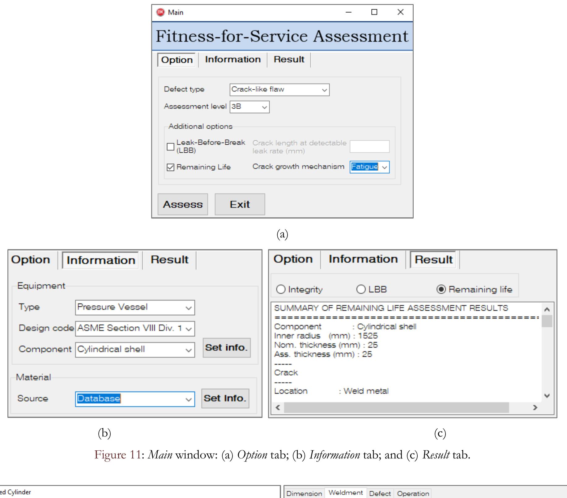
- Methodology: Detailed mathematical formulas, stress classification, and computerized calculations executed using dedicated FFS software or spreadsheets.
- Application: Performed by qualified plant engineers or asset integrity specialists. Level 2 allows for precise calculation of the Remaining Strength Factor (RSF) and maximum allowable working pressure (MAWP).
Level 3 Assessment
Level 3 is the most advanced evaluation level. It provides the highest degree of accuracy by eliminating the generalized assumptions embedded in lower-tier methods.
- Input Data: High-resolution non-destructive evaluation, advanced material testing (e.g., actual yield/tensile strength, Charpy V-notch impact energy, or fracture toughness testing), and precise cyclic loading histories.
- Methodology: Numerical modeling, including Elastic-Plastic Finite Element Analysis (FEA), advanced computational fluid dynamics (CFD), and specialized fracture mechanics software.
- Application: Reserved for high-value assets, critical pressure vessels, severe cracking, complex geometry interactions, or high-temperature creep regimes. Level 3 evaluations require experienced stress analysis specialists and mechanical engineering subject-matter experts.
Major Flaw Types and Damage Mechanisms Covered
API 579-1/ASME FFS-1 is organized into specific parts, each dedicated to evaluating a distinct flaw type or operational degradation mechanism. Understanding these specific parts ensures that inspectors and engineers apply correct damage mechanics principles.
| Part | Technical Subject | Part | Technical Subject |
|---|---|---|---|
| Part 3 | Brittle Fracture | Part 9 | Crack-Like Flaws |
| Part 4 | General Metal Loss | Part 10 | Creep Damage |
| Part 5 | Local Metal Loss (LTA) | Part 11 | Fire Damage |
| Part 6 | Pitting Corrosion | Part 12 | Dents & Gouges |
| Part 7 | Hydrogen Damage & Blistering | Part 13 | Laminations |
| Part 8 | Weld Misalignment & Distortions | Part 14 | Fatigue Assessment |
1. Brittle Fracture Assessment (Part 3)
Part 3 evaluates the risk of catastrophic brittle fracture in carbon and low-alloy steel equipment operating at reduced temperatures or possessing low impact toughness. It establishes safe Minimum Design Metal Temperature (MDMT) limits to ensure operating stresses do not initiate sudden brittle rupture.
2. General and Localized Metal Loss (Parts 4 & 5)
- General Metal Loss (Part 4): Evaluates uniform corrosion or erosion across large surface areas. The analysis focuses on verifying whether remaining wall thickness satisfies minimum structural requirements for primary membrane stresses.
- Local Metal Loss (Part 5): Evaluates localized thin areas (LTAs), grooves, and broad pits. Part 5 utilizes thickness profile mapping along longitudinal and circumferential inspection lines to determine if surrounding sound metal provides sufficient reinforcement.
3. Pitting Corrosion and Laminations (Parts 6 & 13)
- Pitting Corrosion (Part 6): Addresses localized pit clusters where metal loss is isolated to small dimensions. The standard provides formulas to convert pit depth and distribution density into an equivalent uniform metal loss or structural reduction factor.
- Laminations (Part 13): Evaluates planar volumetric defects formed during plate manufacturing. Assessment procedures verify whether laminations run parallel to shell surfaces or step through the wall thickness toward high-stress regions.
4. Hydrogen Blistering and Hydrogen Damage (Part 7)
Hydrogen damage occurs in environments where atomic hydrogen diffuses into steel, forming molecular hydrogen gas at internal voids or inclusions. Part 7 covers hydrogen blisters, Hydrogen-Induced Cracking (HIC), and Stress-Oriented Hydrogen-Induced Cracking (SOHIC), assessing their impact on structural load capacity and rupture potential.
5. Weld Misalignment and Shell Distortions (Part 8)
Fabrication, installation, or operational stresses often induce geometric distortions, such as longitudinal weld angular peaking, shell out-of-roundness, or localized flat spots. Part 8 quantifies the secondary bending stresses induced by these shape deviations under internal pressure.
6. Crack-Like Flaws (Part 9)
Part 9 provides linear-elastic and elastic-plastic fracture mechanics (EPFM) methodologies to evaluate sharp planar flaws, including fatigue cracks, stress corrosion cracking (SCC), and original manufacturing weld defects. It calculates stress intensity factors ($K_I$) and failure assessment diagrams (FAD) to predict critical crack sizes and remaining fatigue life.
7. Creep Damage and Thermal Degradation (Parts 10 & 11)
- Creep Damage (Part 10): Applies to components operating within high-temperature creep regimes where materials undergo time-dependent permanent deformation and microstructural void formation.
- Fire Damage (Part 11): Establishes protocol for evaluating pressure equipment exposed to accidental plant fires, evaluating material softening, distortion, microstructural phase changes, and residual strength loss.
8. Dents, Gouges, and Combined Defects (Part 12)
Mechanical impacts during maintenance, transport, or operational contact often introduce physical dents, deep surface gouges, or combined dent-gouge flaws. Part 12 quantifies localized strain concentrations and residual stress fields to prevent premature mechanical fatigue or plastic collapse.
Step-by-Step Methodology for Conducting an FFS Evaluation
Executing an API 579 assessment requires a disciplined engineering sequence to ensure all operational inputs, stress distributions, and damage profiles are accounted for.
- Step 1: Flaw Identification & NDT Field Data Collection
- Step 2: Operational & Material History Retrieval
- Step 3: Damage Mechanism & Part Selection
- Step 4: Select Assessment Level (Level 1, 2, or 3)
- Step 5: Perform Stress Analysis & Calculate RSF / MAWP
- Step 6: Determine Remaining Safe Life & Inspection Intervals
- Step 7: Implement Rerating, Repair, or Monitoring Strategy
Step 1: Flaw Identification and NDT Data Collection
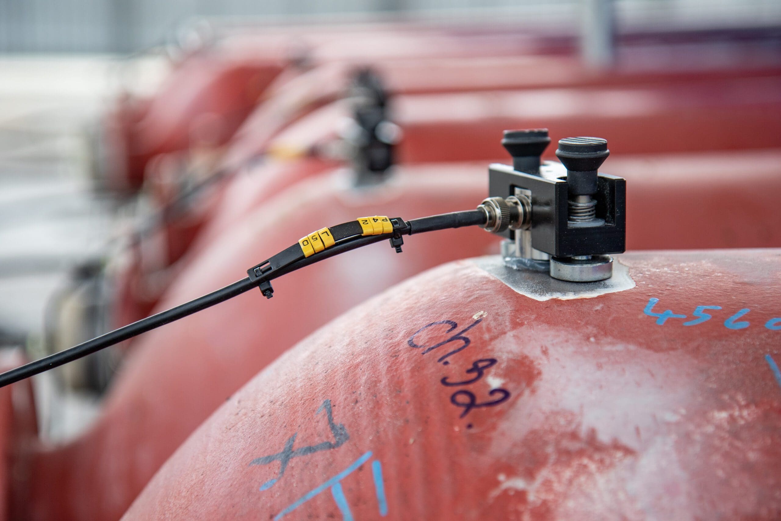
Accurate flaw characterization forms the foundation of every assessment. Inspectors utilize advanced Non-Destructive Testing (NDT) techniques—such as Phased Array Ultrasonic Testing (PAUT), Automated Ultrasonic Testing (AUT), Time-of-Flight Diffraction (TOFD), Radiography (RT), or Eddy Current Testing—to capture precise defect dimensions, depth, orientation, and spatial arrangement.
Step 2: Operational History and Material Data Retrieval
Engineers collect design and operational records, including:
- Original construction drawings and ASME Manufacturer's Data Reports (Form U-1).
- Design pressure, Maximum Allowable Working Pressure (MAWP), operating temperature profiles, and thermal transient histories.
- Material specification sheets, heat numbers, chemical compositions, and original tensile/yield properties.
- Cyclic loading profiles (pressure fluctuations and thermal cycling history).
Step 3: Damage Mechanism Identification
Before applying calculation formulas, engineers must confirm the root cause of degradation. Misidentifying active mechanisms—such as treating active environmental cracking as static localized corrosion—can result in unsafe conclusions.
Step 4: Assessment Level Selection
Choose between Level 1, Level 2, or Level 3 based on flaw severity, equipment criticality, and available data. If initial screening under Level 1 fails, the evaluation escalates to Level 2 or Level 3.
Step 5: Stress Analysis and RSF Calculation
The core metric in API 579 evaluations is the Remaining Strength Factor (RSF). The RSF is defined as the ratio of the burst pressure (or plastic collapse load) of the damaged component to the burst pressure of the component in its original, undamaged state:
$$\text{RSF} = \frac{L_{\text{damaged}}}{L_{\text{undamaged}}}$$
The standard establishes an allowable Remaining Strength Factor, typically set at $RSF_a = 0.90$ for pressurized components.
- If $\text{RSF} \ge RSF_a$, the damaged component is structurally capable of operating at its full original MAWP.
- If $\text{RSF} < RSF_a$, the component's maximum allowable working pressure must be reduced (derated), or the flaw must be repaired or reinforced. The reduced allowable operating pressure ($MAWP_r$) is calculated as:
$$MAWP_r = MAWP \times \left( \frac{\text{RSF}}{RSF_a} \right)$$
Step 6: Remaining Safe Life and Inspection Interval Determination
By combining calculated wall loss or crack growth rates with future corrosion allowances, engineers project the component's remaining safe operating life. In-service inspection codes like API 510 dictate that maximum inspection intervals should not exceed half of the calculated remaining safe life.
Step 7: Mitigation, Repair, or Rerating Implementation
When an assessment demonstrates that a component cannot sustain continued operation safely, integrity engineers select appropriate interventions, such as:
- Operating Derate: Reducing internal pressure or adjusting Minimum Design Metal Temperature (MDMT).
- Physical Repair: Executing ASME PCC-2 compliant repairs, such as metallic sleeve installation, weld overlay, flush patch replacement, or composite wrap application.
- Remediation & Monitoring: Modifying chemical treatment, installing corrosion inhibitors, or implementing real-time online UT thickness monitoring.
Comparison of API 579 Assessment Levels
The following matrix illustrates key differences between Level 1, Level 2, and Level 3 Fitness-For-Service assessment tiers:
| Parameter / Feature | Level 1 Assessment | Level 2 Assessment | Level 3 Assessment |
|---|---|---|---|
| Primary Goal | Rapid, conservative screening | Detailed engineering evaluation | Advanced optimization & exact stress modeling |
| Conservatism Level | Highest conservatism | Moderate conservatism | Lowest conservatism (Most realistic) |
| Data Requirements | Minimal (basic NDT, $t_{min}$, design parameters) | Detailed (UT thickness grid mapping, flaw profiles) | High-resolution NDT, material toughness testing, transient data |
| Analytical Tools | Standard look-up tables, simple hand formulas | Detailed closed-form equations, spreadsheet models | Elastic-Plastic FEA, specialized fracture mechanics software |
| Required Expertise | Plant Inspectors, QA/QC Technicians, Integrity Engineers | Asset Integrity Engineers, Mechanical Engineers | Advanced Finite Element Analysts, Subject Matter Experts |
| Time & Execution Cost | Minimal time; low cost | Moderate time; intermediate cost | Significant time; high specialized cost |
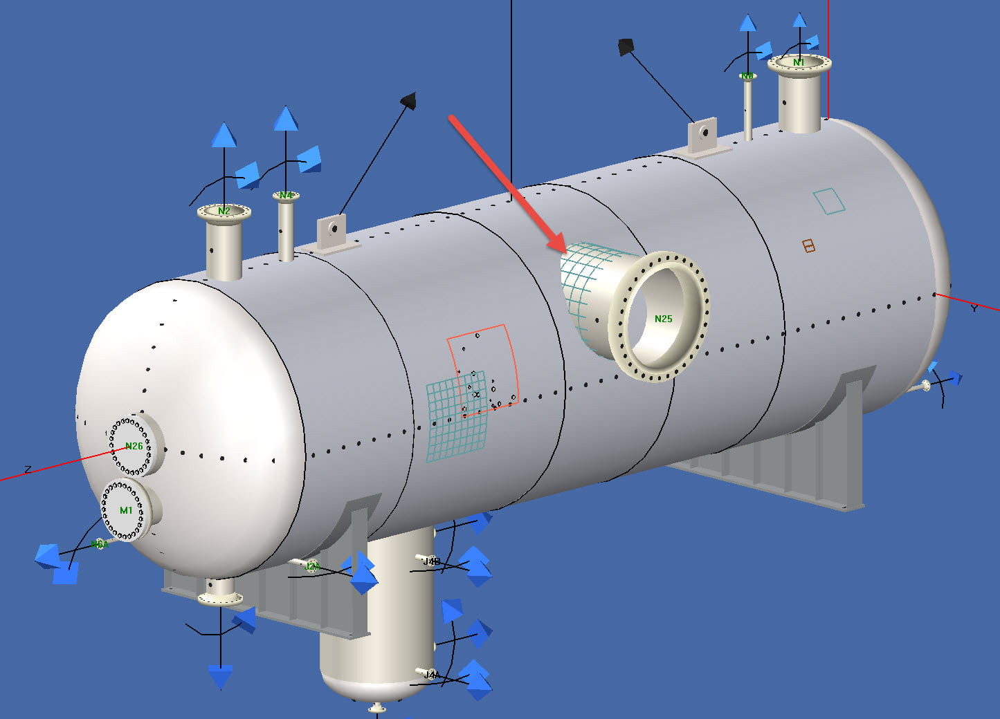
| Typical Application | Uniform wall thinning, simple local metal loss | Complex thinning profiles, local misalignment, weld defects | Severe crack-like flaws, high thermal cycling, complex pressure vessel nozzles |
Integration with Design Codes and Inspection Standards
API 579-1/ASME FFS-1 does not replace original equipment design codes or in-service inspection codes; rather, it complements them. It serves as an analytical bridge between construction rules and operational maintenance.
- ORIGINAL DESIGN CODES (ASME Sec VIII, ASME B31.3, API 650 / 620)
- IN-SERVICE INSPECTION CODES (API 510, API 570, API 653)
- (Flaw / Damage Exceeds Tolerances)
- FITNESS-FOR-SERVICE ASSESSMENT (API 579-1 / ASME FFS-1)
- (If Repair Is Required)
- REPAIR & ALTERATION CODES (ASME PCC-2, API 510/570)
Relationship to Design Codes
Equipment is originally designed according to rules-based codes such as ASME Boiler and Pressure Vessel Code (BPVC) Section VIII (Division 1 and Division 2), ASME B31.3 (Process Piping), or API 650 (Welded Tanks for Oil Storage). Design codes mandate conservative safety factors intended for new construction. API 579 applies refined engineering principles to calculate real structural limits once defects appear during service.
Relationship to In-Service Inspection Codes
In-service inspection standards—specifically API 510 (Pressure Vessel Inspection), API 570 (Piping Inspection), and API 653 (Tank Inspection)—define mandatory maintenance schedules, thickness limits, and inspection intervals. When routine inspection reveals wall thinning below the original minimum calculated thickness ($t_{min}$) or uncovers planar crack-like indications, inspection standards explicitly direct engineers to API 579 to perform a formal Fitness-For-Service assessment.
Guidance on Repairs and Rerating
If an API 579 evaluation determines that structural restoration is required, repair design and installation procedures are governed by standards such as ASME PCC-2 (Repair of Pressure Equipment and Piping) alongside repair provisions within API 510, 570, or 653.
Common Pitfalls and Best Practices in FFS Evaluations
To maintain structural integrity while avoiding unnecessary capital expenditure, asset integrity managers should account for several critical operational considerations during FFS evaluations.
Common Pitfalls
- Misidentifying Damage Mechanisms: Evaluating an active Stress Corrosion Cracking (SCC) flaw using Part 5 (Local Metal Loss) formulas instead of Part 9 (Crack-Like Flaws) will severely underestimate structural failure risks.
- Inadequate Inspection Grid Density: Taking insufficient thickness measurements across a localized thin area can cause engineers to miss the true point of minimum remaining wall thickness.
- Ignoring Future Degradation Rates: An FFS evaluation proves equipment is safe at the moment of inspection. Failing to account for ongoing corrosion rates will cause premature operational failure before the next scheduled inspection.
- Assuming Static Operating Conditions: Evaluating fatigue or creep damage without factoring in pressure spikes, thermal transients, or startup/shutdown cycles leads to invalid remaining life projections.
Best Practices for Engineering Teams
- Validate NDT Precision: Ensure non-destructive testing technicians are qualified in advanced techniques and that equipment calibrations account for temperature variations and surface roughness.
- Perform Sensitivity Analyses: When material properties (such as Charpy impact energy or yield strength) must be estimated from historical databases, conduct sensitivity studies using bounding conservative assumptions.
- Document Evaluation Assumptions: Maintain permanent engineering records detailing all stress formulas, software versions, NDT datasets, and boundary conditions applied during Level 1, 2, or 3 assessments.
- Implement Continuous Monitoring: Pair FFS evaluations with online corrosion monitoring, automated UT sensors, or key process variable (KPV) limits to verify that operating conditions remain within assumed assessment parameters.
Frequently Asked Questions
What is the main difference between API 579 Level 1, Level 2, and Level 3 assessments?
Level 1 is a conservative screening method intended for rapid field use by inspection personnel using standard look-up tables. Level 2 uses detailed mathematical formulas and point-by-point inspection grids, requiring engineering calculations. Level 3 uses advanced numerical methods—such as Finite Element Analysis (FEA) and specialized fracture mechanics—to provide the most accurate assessment with the lowest conservatism.
When is an API 579 Fitness-For-Service assessment required?
An assessment is required whenever routine inspection uncovers flaws, volumetric wall loss, cracking, mechanical deformation, or fire damage that exceeds original code design allowances defined in API 510, API 570, API 653, or ASME design codes. It is also executed prior to re-rating operating pressures or extending equipment service life.
How does API 579 recalculate Maximum Allowable Working Pressure (MAWP)?
API 579 calculates the Remaining Strength Factor (RSF) of the damaged component. If the calculated RSF is less than the allowable threshold (typically $RSF_a = 0.90$), the original MAWP is reduced proportionally ($MAWP_r = MAWP \times [\text{RSF} / RSF_a]$) to maintain required safety margins.
Can API 579 be applied to crack-like flaws in pressure vessels?
Yes, Part 9 of API 579-1/ASME FFS-1 provides detailed fracture mechanics procedures for evaluating planar crack-like flaws. It evaluates linear-elastic stress intensity factors and uses Failure Assessment Diagrams (FAD) to determine whether a crack risks unstable fast fracture or plastic collapse.
What is Remaining Strength Factor (RSF) and why is it critical?
The Remaining Strength Factor is the ratio of the failure load of a damaged component to the failure load of the same component in its undamaged condition. It provides a standardized structural integrity index that allows engineers to decide whether damaged equipment can continue operating without repair or pressure derating.
Practical Recommendations for Plant Integrity Managers
To maximize asset life while ensuring absolute operational safety, processing facilities should adopt a systematic approach to Fitness-For-Service management:
- Establish Clear Escalation Protocols: Train plant inspectors to identify when degradation exceeds simple code allowances so that issues are promptly escalated from Level 1 field screening to Level 2 or Level 3 engineering teams.
- Standardize Data Collection Templates: Standardize NDT thickness grid formats, flaw profile documentation, and operational data retrieval to ensure seamless input into FFS software tools.
- Audit Engineering Software and FEA Models: Ensure third-party engineering contractors performing Level 2 and Level 3 assessments strictly adhere to API 579-1/ASME FFS-1 procedures and validate FEA mesh convergence and boundary conditions.
- Integrate FFS Outcomes into Management of Change (MOC): Any operational modifications resulting from an FFS study—such as pressure deratings, reduced temperature limits, or specialized chemical inhibition—must be fully documented in the facility’s MOC system and updated in process safety control loops.