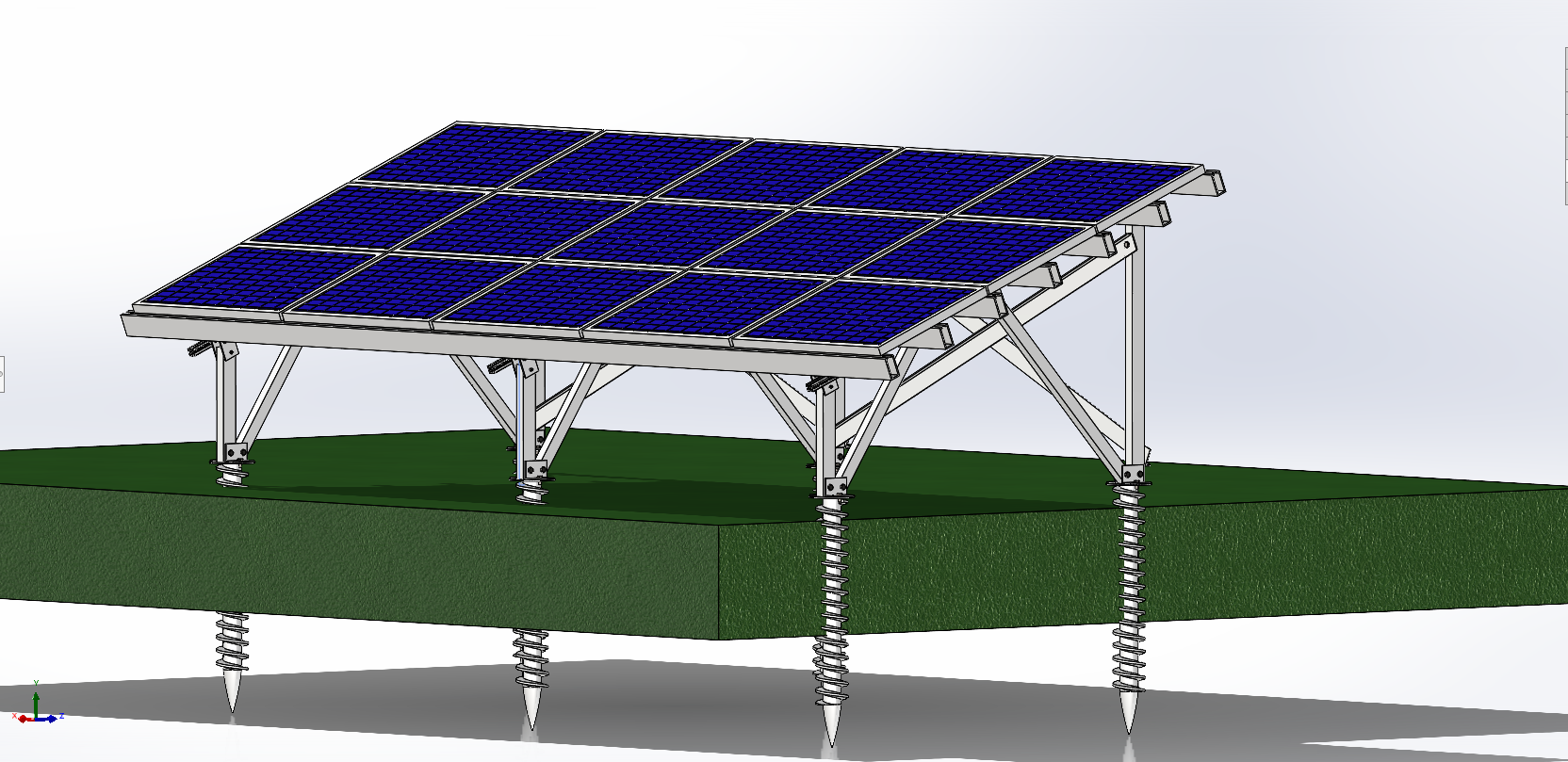
Transitioning to a 10kW solar power system requires evaluating various structural configurations, among which ground-mounted arrays offer superior optimization, maintenance accessibility, and positioning flexibility compared to traditional rooftop installations. The 10kW solar panel ground mount installation kit by GoGreenSolar provides a pre-engineered structural hardware package designed to anchor a residential or small commercial photovoltaic array directly into the earth. This overview examines the components, site requirements, structural design, logistical considerations, and practical implications of deploying this specific kit.
Understanding the GoGreenSolar 10kW Ground Mount System
A 10kW ground-mounted solar array is a substantial energy generation project, typically consisting of 24 to 30 individual photovoltaic panels depending on the wattage of the chosen modules. The hardware required to support this weight securely against wind, snow, and seismic forces must be meticulously engineered. GoGreenSolar structures these kits to streamline the procurement process by bundling structural rails, mounting clamps, vertical support posts, and hardware fasteners into a single package.
Unlike rooftop systems that rely on existing rafters and roofing penetration seals, ground mounts require a dedicated foundation. The GoGreenSolar kit generally utilizes structural steel pipes or specialized ground screws, depending on the specific sub-variant ordered, to anchor the array framework. Understanding what is included—and what must be sourced locally—is vital for project planning. While the kit provides the above-ground racking, rails, and module clamps, the concrete required for footings or heavy equipment rentals for driving ground anchors typically falls outside the standard package scope.
Key Technical Components and Structural Architecture
The engineering integrity of a ground mount depends heavily on how forces are transferred from the solar panels down to the earth. The GoGreenSolar installation kit utilizes a robust mechanical architecture comprising several foundational layers.
Structural Support Rails and Framing
The backbone of the mounting surface consists of heavy-gauge extruded aluminum rails. These rails are engineered to span distances between vertical support posts while resisting the bending moments caused by wind uplift. The rails feature integrated channel slots that accept T-bolts or specialized mounting hardware, allowing installers to secure mid-clamps and end-clamps efficiently.
Vertical Posts and Foundation Anchors
Depending on the soil conditions and engineering requirements, the system relies on heavy-duty steel piping anchored via concrete piers or driven earth screws. Concrete piers require augering holes below the local frost line, inserting vertical steel columns, and pouring high-strength concrete. This method creates a rigid cantilevered structure capable of withstanding heavy environmental loads.
Module Clamps and Fastening Hardware
Securing the solar panels to the aluminum rails requires specialized hardware. The kit includes anodized aluminum mid-clamps and end-clamps designed to fit standard solar panel frame thicknesses (typically 30mm to 40mm). These clamps often incorporate grounding clips or bonding pins to ensure that the entire array forms a continuous electrical ground path, satisfying National Electrical Code (NEC) requirements for equipment grounding.
Site Assessment and Pre-Installation Requirements
Before ordering or unpacking a 10kW ground mount kit, a thorough site assessment is non-negotiable. Ground-mounted systems require significantly more space than rooftop arrays and are subject to strict local zoning laws, setback requirements, and utility interconnection rules.
Space Requirements and Solar Access
A 10kW system utilizing modern 400W panels requires approximately 500 to 700 square feet of unobstructed, south-facing surface area (in the Northern Hemisphere). Shadows from trees, neighboring structures, or utility poles can severely degrade system performance due to string-inverter configuration limitations or module-level mismatch. Installers must perform a rigorous solar shadow analysis using a Solar Pathfinder or digital equivalent across all seasonal sun paths.
Geotechnical and Soil Analysis
The stability of a ground mount depends entirely on the soil matrix. Clay, sand, rock, and organic topsoil all react differently to structural loads.
- Rocky Terrain: May necessitate specialized rock-drilling equipment or alternative ballasted mounting solutions.
- High-Water-Table Soils: Require deeper concrete footings or corrosion-resistant galvanized steel components to prevent premature degradation.
- Sloped Land: Requires leveling strategies or adjustable racking legs to accommodate grade changes across the array footprint.
Permitting and Utility Interconnection
Ground mounts almost universally require structural building permits, electrical permits, and zoning approvals from local municipal authorities. Engineers must stamp the layout drawings to verify that the wind speed ratings (often rated for 90 to 130 mph depending on regional codes) and snow load tolerances meet local building codes. Concurrently, an interconnection application must be submitted to the local electric utility to ensure the grid can accept a 10kW backfeed.
Step-by-Step Installation Workflow
Executing a ground mount installation requires a coordinated sequence of civil, mechanical, and electrical tasks. While the structural kit simplifies the mechanical assembly, strict adherence to engineering drawings is mandatory.
1. Site Layout & Excavation -> 2. Foundation Installation -> 3. Post & Racking Assembly -> 4. Electrical Integration
1. Site Layout and Excavation
Using stakes, mason’s string, and a transit level, mark the exact locations for the vertical support posts according to the engineering diagram. Accuracy in squaring the layout is critical; out-of-square framing will prevent the solar panels from sitting flush on the rails. Excavate holes to the depth specified by local frost-line regulations and engineering guidelines.
2. Foundation and Post Setting
Position the vertical steel support pipes into the excavated holes, leveling and bracing them temporarily with wood framing. Pour structural concrete into the footings, ensuring no voids form around the steel. Allow the concrete to cure fully—typically 7 to 14 days depending on ambient temperature and concrete mix design—before applying heavy mechanical loads to the posts.
3. Racking and Rail Assembly
Bolt the horizontal cross-beams and structural rails to the vertical posts using the heavy-duty hardware provided in the kit. Check diagonal measurements across the rail frame to ensure it is perfectly square. Torque all bolts to the manufacturer’s specified foot-pounds using a calibrated torque wrench to prevent slippage under thermal expansion and contraction.
4. Panel Placement and Electrical Wiring
Mount the photovoltaic modules onto the rails, working systematically from one side to the other. Fasten the mid-clamps between adjacent panels and end-clamps at the array perimeters. Route the DC homerrun wires through protective conduit down to the inverter or combiner box, ensuring all wire management avoids sharp metal edges and contact with the ground.
Comparative Overview of Mounting Strategies
Selecting the correct mounting methodology involves weighing upfront material and labor costs against long-term operational efficiency. The following table contrasts ground mounts with alternative configurations.
| Metric / Feature | GoGreenSolar 10kW Ground Mount | Standard Roof Mount | Pole-Mounted Tracking System |
|---|---|---|---|
| Land / Space Footprint | Requires dedicated open ground space (~600 sq ft) | Utilizes existing roof real estate | Requires open ground space (~500 sq ft) |
| Installation Complexity | Moderate to High (Earth excavation, concrete) | Moderate (Roof penetrations, fall safety) | High (Deep single-pole augering, moving parts) |
| Cooling & Efficiency | Excellent natural airflow underneath panels | Lower airflow; trapped heat reduces efficiency | Excellent airflow around elevated panels |
| Maintenance Access | Easy ground-level cleaning and servicing | Difficult; requires ladder or roof safety gear | Moderate to difficult due to elevation and mechanics |
| Upfront Civil Costs | Higher due to trenching and concrete footings | Lower structural preparation costs | Highest due to heavy mechanical actuators and deep piers |
Practical Limitations and Common Challenges
While ground mounts offer clear operational advantages, prospective buyers should account for practical hurdles that can impact project timelines and budgets.
Trenching and Balance of System (BOS) Costs
Because ground mounts are typically located yards or even hundreds of feet away from the main electrical service panel, DC and AC wiring must be run underground. This requires trenching to a depth compliant with local electrical codes (often 18 to 24 inches deep), laying PVC conduit, pulling heavy-gauge copper wire, and backfilling. Trenching labor and materials represent a significant portion of the total Balance of System cost that is not included in the basic rack kit.
Vegetation and Weed Management
Placing a solar array close to the ground creates shaded, damp microclimates underneath the panels where weeds, grass, and brush thrive. Unchecked vegetation growth can shade the lower edge of the panels, creating hot spots and string power losses. Property owners must plan for ongoing vegetation management, such as laying weed-barrier fabric covered with crushed gravel, planting low-growth ground cover, or manual trimming.
Aesthetic and Line-of-Sight Restrictions
Unlike rooftop systems that blend into the roofline, ground mounts are highly visible. Some Homeowners Associations (HOAs) or municipal planning boards enforce strict aesthetic guidelines regarding where ground arrays can be placed, often requiring privacy fencing or landscape screening to obscure them from neighboring properties.
Frequently Asked Questions
Can I install the GoGreenSolar 10kW ground mount kit myself?
Yes, the kit is designed for DIYers with strong construction skills, but heavy equipment like a post-hole digger, concrete mixer, and transit level are typically required. Hiring licensed electricians for the final grid tie-in is mandatory in most jurisdictions.
How deep do the concrete footings need to be?
Footing depth depends entirely on local frost lines and wind load requirements specified in your site-specific engineering report. In colder climates, footings must extend below the maximum frost depth to prevent frost heaving, often ranging from 24 to 48 inches deep.
Can the tilt angle of the GoGreenSolar mount be adjusted seasonally?
Standard fixed-tilt ground mount kits are engineered for a static angle calculated to optimize annual energy production based on local latitude. While some custom racking systems allow manual seasonal tilt adjustments, standard kits are locked into a single fixed angle once bolted down.
What kind of maintenance does a ground-mounted array require?
Maintenance is relatively minimal but includes periodic visual inspections of structural hardware torque, checking electrical connections for corrosion, cleaning dust or debris off the glass surfaces, and keeping weeds trimmed away from the lower array perimeter.
Does the 10kW kit include the solar panels and inverter?
GoGreenSolar offers various kit configurations; some packages include panels and inverters (complete kits), while others consist strictly of the structural racking hardware (mount-only kits). Buyers must carefully verify the exact bill of materials included in their specific order confirmation.
Conclusion and Next Actions
Deploying a 10kW solar panel ground mount installation kit by GoGreenSolar is an effective strategy for maximizing clean energy production without compromising roof integrity. Success relies on meticulous upfront preparation: verifying local zoning laws, conducting a thorough soil and shadow analysis, and budgeting adequately for foundational concrete and underground trenching. Before purchasing, secure professional engineering stamps if required by your municipality, and coordinate closely with your local utility provider to ensure a smooth interconnection process.