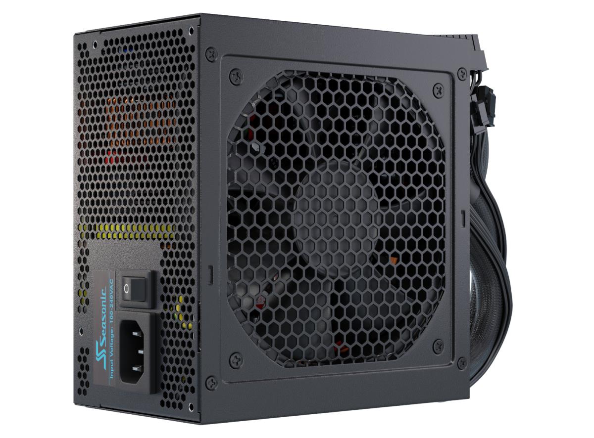
Understanding ATX power supply specifications requires evaluating core electrical performance parameters—including voltage regulation, ripple suppression, hold-up time, and efficiency certifications—alongside physical form factors and dynamic load capabilities. Key requirements ensure stable power delivery under variable workloads, with modern standards like ATX 3.0 and ATX 3.1 establishing strict peak power excursion thresholds and updated safety-focused high-power cabling standards.
The Evolution of ATX Power Supply Specifications
The Advanced Technology Extended (ATX) power supply specification, originally established by Intel, serves as the standard design guide for desktop PC power supplies (PSUs). Over decades, desktop computing demands have shifted from high current on the lower voltage rails (+5V and +3.3V) to extreme current demands on the +12V rail, driven by modern graphics processing units (GPUs) and high-core-count central processing units (CPUs).
ATX Specification Evolution:
- ATX 2.x Standard
- Focus: +12V Multi/Single Rail
- Cable: PCIe 6+2 Pin
- Regulation: Basic ±5%
- ATX 3.0 Standard
- Focus: 200% Power Excursions
- Cable: 12VHPWR (12+4 Pin)
- Efficiency: ALPM / Low Load
- ATX 3.1 Standard
- Focus: Refined Hold-Up Timing
- Cable: 12V-2x6 (PCIe 5.1)
- Enhanced Connector Safety
Legacy ATX 2.x Specifications
The ATX 2.x standards (including popular revisions like ATX 2.3, 2.4, and 2.52) governed PC power design for over fifteen years. Under ATX 2.x, power supplies were rated primarily based on continuous DC output wattage. However, modern system components, particularly high-end GPUs, present dynamic power demands characterized by rapid microsecond power spikes—known as transient loads or power excursions. Legacy ATX 2.x units lacked formal testing requirements for high-amplitude transients, leading to unexpected system shutdowns even on units with high overall wattage ratings.
The Modern Shift: ATX 3.0 and ATX 3.1
Intel introduced the ATX 3.0 specification to address the electrical demands of PCIe 5.0 hardware. ATX 3.0 mandated that power supplies sustain transient power spikes up to 200% of their rated total wattage for 100 microseconds ($\mu\text{s}$). It also introduced the native 16-pin 12VHPWR connector capability to deliver up to 600 Watts over a single cable.
The revised ATX 3.1 specification refined these requirements. ATX 3.1 replaced the initial 12VHPWR cable design with the updated 12V-2x6 connector (standardized under PCIe 5.1) to resolve mechanical and thermal issues caused by improper cable seating. Additionally, ATX 3.1 adjusted hold-up time mandates and lowered transient response thresholds under specific operational modes, offering PSU manufacturers design flexibility to improve light-load efficiency and thermal output without sacrificing system stability.
Core Electrical Parameters and Requirements
A power supply converts incoming alternating current (AC) from a wall outlet into smooth, low-voltage direct current (DC) required by internal components. Evaluating a PSU specification sheet requires an understanding of its underlying electrical metrics.
1. Voltage Rails and Output Distribution
Modern ATX power supplies supply several distinct DC output voltages:
- +12V Rail: The most critical output in modern systems. Powers the CPU, GPU, cooling pumps, and fans. Modern high-tier power supplies often utilize a Single +12V Rail design (where all 12V capacity is directed through one circuit) or a Multi-Rail +12V design (where independent over-current protection limits are set on individual output groupings for enhanced safety).
- +5V and +3.3V Rails: Used for solid-state drives (SSDs), RGB lighting controllers, motherboard logic, and legacy peripherals. Modern power supplies generate these voltages using a DC-to-DC Converter topology off the primary +12V rail, rather than converting them directly from AC. This ensures independent regulation regardless of the load on the +12V rail.
- +5VSB (+5V Standby): Supplies trickle power to the motherboard even when the main system is powered down, enabling features like Wake-on-LAN, power button state detection, and USB power while sleeping.
- -12V Rail: A legacy rail maintained primarily for legacy expansion card requirements and certain integrated audio circuits, typically limited to 0.3A–0.5A.
2. Voltage Regulation Tightness
Voltage regulation measures how consistently a power supply maintains nominal rail output voltages as the load varies from zero to full capacity.
- Intel ATX Standard: Mandates a maximum allowable deviation of $\pm$5% on positive output rails (+12V, +5V, +3.3V).
- High-Performance Standard: Top-tier power supplies achieve $\pm$1% to $\pm$2% regulation (often referred to as "tight regulation"). Precise voltage stability prevents system crashes, memory errors, and unnecessary heat accumulation in motherboard Voltage Regulator Modules (VRMs).
3. Ripple and Noise Suppression
DC output voltages are not completely flat; they contain small residual AC fluctuations called ripple (periodic fluctuations caused by high-frequency switching circuits) and high-frequency noise spikes.
- ATX Maximum Limits: Limits ripple and noise to 120 mV peak-to-peak (p-p) on the +12V and -12V rails, and 50 mV p-p on the +5V, +3.3V, and +5VSB rails across a 20 MHz bandwidth.
- Optimal Performance: Premium power supplies keep +12V ripple below 20 mV to 30 mV p-p. High ripple degrades solid-state capacitors over time, compromises extreme CPU/GPU overclocking, and can cause random system instability under heavy load.
4. Hold-Up Time and Power-Good (PWR_OK) Signal
Hold-up time refers to the duration (in milliseconds) that a power supply can continue delivering within-spec DC power after a complete loss of AC input electricity (such as a minor brownout or short line dropout).
Timeline of Power Loss Event:
- AC Mains Power Failure
- Hold-Up Time Window (e.g., ≥ 16 ms)
- Output voltages (+12V, +5V, +3.3V) remain inside safe DC limits
- PWR_OK Signal Drops Low (Must occur at least 1ms before DC rails collapse)
- Motherboard senses PWR_OK loss and initiates orderly system shutdown
- DC Rail Output Voltage Collapses
- Hold-Up Time Window (e.g., ≥ 16 ms)
- Hold-Up Time Mandate: Historically specified as a minimum of 16ms at 100% rated load.
- PWR_OK Signal Timing: The power supply outputs a digital
PWR_OK(Power-Good) signal to the motherboard once output voltages settle within safe ranges. Under ATX guidelines, thePWR_OKsignal must remain high for at least 16ms during a power interrupt and must drop low at least 1ms before output voltages fall out of regulation limits. This 1ms cushion alerts the motherboard to execute a safe reset sequence, protecting stored data and preventing file-system corruption.
Transient Response and Power Excursions
Modern graphic processors shift between low-power idle states and high-frequency burst processing within nanoseconds. These sudden changes in power consumption induce immediate transient load spikes.
Dynamic Power Excursion Profile (ATX 3.0 / 3.1 Spec):
- Wattage Output
- 200% (Transient Peak: 100 µs limit)
- 100% (Nominal Rating)
- 0%
- Time
Understanding Transient Spikes
When a GPU requests a sudden surge of current, the power supply's output voltage momentarily drops (undershoot). Conversely, when the GPU load collapses instantly, output voltage rises (overshoot). If the PSU's internal control loop responds slowly, the voltage undershoot will drop below the standard $\pm$5% operating threshold, causing system crashes or triggering the graphics driver to reset.
ATX 3.0 and 3.1 Power Excursion Benchmarks
To withstand high transient behavior, the ATX 3.0/3.1 standards enforce specific excursion limits relative to nominal rating:
- 100 $\mu\text{s}$ Peak Excursion: The PSU must supply up to 200% of its rated continuous power for a $100,\mu\text{s}$ window at a 10% duty cycle.
- Sustained Lower Duration Spikes: The PSU must support 180% load for 1 ms, 160% load for 10 ms, and 120% load for 100 ms.
- PCIe Slot and Cable Limits: Specific high-power PCIe interfaces must accommodate transient spikes up to 300% of the rated power delivered strictly through the graphics expansion cable.
Efficiency Certifications: 80 PLUS and Cybenetics
Power supply efficiency measures the ratio of output DC power delivered to components relative to the total input AC power drawn from the electrical outlet. Unconverted energy is dissipated as waste heat.
$$\text{Efficiency (%)} = \left( \frac{\text{DC Power Delivered to PC (Watts)}}{\text{AC Power Drawn from Outlet (Watts)}} \right) \times 100$$
80 PLUS Efficiency Standard
The long-standing 80 PLUS certification program classifies PSUs based on test results at specified load points (20%, 50%, and 100% rated load) along with Power Factor Correction (PFC) minimums.
| 80 PLUS Level | 20% Rated Load (115V Internal) | 50% Rated Load (115V Internal) | 100% Rated Load (115V Internal) | Power Factor at 100% Load |
|---|---|---|---|---|
| 80 PLUS White | 80% | 80% | 80% | 0.90 |
| 80 PLUS Bronze | 82% | 85% | 82% | 0.90 |
| 80 PLUS Silver | 85% | 88% | 85% | 0.90 |
| 80 PLUS Gold | 87% | 90% | 87% | 0.90 |
| 80 PLUS Platinum | 90% | 92% | 89% | 0.95 |
| 80 PLUS Titanium | 90% (at 10% load) / 92% | 94% | 90% | 0.95 |
Note: Operational testing under 230V input yields approximately 1% to 2% higher overall efficiency figures due to reduced AC amperage losses.
Cybenetics Certification (ETA and LAMBDA)
The Cybenetics standard provides an alternative certification framework designed to evaluate PSUs across thousands of load combinations, including low-load conditions (10W to 55W) and standby efficiency.
- Cybenetics ETA: Measures overall efficiency, Power Factor (PF), +5VSB efficiency, and standby vampire power draw. Ratings range from Bronze up to Diamond.
- Cybenetics LAMBDA: Evaluates acoustic output measured in decibels (dBA) across the operational envelope. Ratings range from Standard (>40 dBA) down to A++ (<15 dBA).
Essential Power Supply Protections
Safety protection circuits prevent damaged PC components, localized melting, or fire hazards during component failures or utility power anomalies. A fully specified ATX power supply should incorporate all primary protection features:
Integrated PSU Protection Circuitry Matrix:
- OCP (Over-Current Protection)
- OVP (Over-Voltage Protection)
- UVP (Under-Voltage Protection)
- OPP (Over-Power Protection)
- OTP (Over-Temperature Protection)
- SCP (Short-Circuit Protection)
- SIP (Surge & Inrush Protection)
- Over-Current Protection (OCP): Shuts down the PSU if current draw on any individual rail exceeds set thresholds. Crucial for multi-rail power supplies to prevent thin wire trace overheating.
- Over-Voltage Protection (OVP): Monitors rail voltages and trips the power unit if DC output rises above standard specification limits (e.g., +12V rail exceeding ~13.4V–15.6V).
- Under-Voltage Protection (UVP): Triggers a shutdown if output voltage drops below safe operating limits under extreme load conditions.
- Over-Power Protection (OPP / OLP): Shuts down the unit if total output wattage exceeds a safe threshold (typically 115%–135% of maximum continuous rating) to protect primary switching transistors.
- Over-Temperature Protection (OTP): Integrates thermistors on internal heatsinks to disable the PSU if internal temperatures exceed safety margins (often due to fan failure or obstructed airflow).
- Short-Circuit Protection (SCP): Constantly monitors output rail impedance; instantly latches the power supply off if resistance drops below $0.1,\Omega$, preventing damage from direct electrical shorts.
- Surge and Inrush Protection (SIP): Uses Metal Oxide Varistors (MOVs) and NTC thermistors to absorb external utility surges and limit initial current spike when switching on.
Form Factors, Modular Cabling, and High-Power Connectors
Physical Form Factors
- Standard ATX: Measures 150 mm (W) x 86 mm (H) with varying depths ranging from 140 mm to 200 mm. Deeper units often accommodate larger 135mm/140mm cooling fans and larger smoothing capacitors.
- SFX (Small Form Factor): Designed for compact chassis, measuring 125 mm (W) x 63.5 mm (H) x 100 mm (D) using a 80mm or 92mm fan.
- SFX-L: Extended SFX footprint with a depth of 125 mm, allowing integration of a 120mm cooling fan for lower noise profiles.
Modular Cabling Types
- Full-Modular: All cables (including main 24-pin motherboard and 8-pin EPS) disconnect from the PSU chassis. Simplifies cable management and custom routing.
- Semi-Modular: Core system cables (24-pin ATX, 8-pin CPU) are hardwired; auxiliary cables (PCIe, SATA, Peripheral) are detachable.
- Non-Modular (Fixed): All wiring harnesses are permanently attached to the internal PCB.
High-Power Graphics Connectors: 12VHPWR vs. 12V-2x6
The transition to high-draw PCIe 5.0 graphics hardware required modern cabling solutions to replace multiple legacy 8-pin (6+2) PCIe cables.
Visual Comparison of High-Power Pin Architectures:
12VHPWR Connector (PCIe 5.0 - Early Standard):
- Power Terminals
- Sense Pins (Standard length - risky if unseated)
12V-2x6 Connector (PCIe 5.1 / ATX 3.1 Standard):
- Power Terminals (Extended engagement depth)
- Sense Pins (Recessed by 1.7mm - safe cut-off)
12VHPWR (CEM 5.0 Standard): Features 12 power pins and 4 signal/sense pins ($S1$--$S4$) capable of delivering up to 600 Watts. However, if the connector was slightly unseated, improper pin engagement led to elevated contact resistance and excessive heat buildup.
12V-2x6 (CEM 5.1 / H++ Standard): The standard featured on ATX 3.1 compliant units. Mechanical modifications include longer power pins to ensure solid electrical contact and shorter (recessed) sense pins by 1.7 mm. If the 12V-2x6 cable is not fully seated, the recessed sense pins lose contact first, preventing the PSU from signaling open power delivery to the GPU and protecting the connection from thermal overload.
Technical Comparison of ATX Specifications
The following table summarizes key technical parameters across major ATX design standard iterations:
| Technical Parameter | Legacy ATX 2.4 / 2.52 | Modern ATX 3.0 | Current ATX 3.1 |
|---|---|---|---|
| Peak Power Excursion (100 $\mu\text{s}$) | Unspecified (~110%–120%) | 200% of rated continuous wattage | 200% of rated continuous wattage |
| GPU Excursion Handling | Standard linear overload limits | Up to 300% transient excursion on GPU cable | Up to 300% transient excursion on GPU cable |
| Native High-Power Cable | None (Uses 8-pin PCIe 6+2) | 12VHPWR (16-pin / 12+4 pin) | 12V-2x6 (PCIe 5.1 / H++ connector) |
| Hold-Up Time Requirement | Minimum 16 ms at 100% load | 17 ms recommended at 100% load | Revised mandatory minimum options (e.g., 12 ms) |
| Alternative Low-Power Mode (ALPM) | Not required | Supported for instant system wake | Supported for optimized low-power states |
| Low-Load Efficiency Requirement | Minimal baseline enforcement | >60% or >70% required at 10W or 2% load | >60% or >70% required at 10W or 2% load |
| Primary Voltage Topologies | Group regulated or DC-DC | DC-DC with Active PFC & LLC | DC-DC with Active PFC & LLC |
How to Calculate Power Requirements and Choose the Right PSU
Determining the required power supply capacity involves balancing real-time component power consumption, transient thermal limits, and efficiency targets.
Step 1: Sum Total Component Power Draw (TDP / TBP)
Calculate maximum baseline thermal power ratings:
- CPU: Base power to Maximum Turbo Power (e.g., 125W base to 253W peak limit).
- GPU: Total Board Power (TBP) rating (e.g., 200W up to 450W+).
- Motherboard, RAM, and Storage: Allocate roughly 50W–70W combined.
- Fans, Liquid Cooling Pumps, AIOs: Allocate 3W–10W per fan/pump.
Step 2: Apply the Efficiency Sweets-Spot Overhead
Power supplies operate at peak electrical conversion efficiency when delivering 40% to 70% of their total rated capacity. Operating within this range also allows internal cooling fans to run at lower, quieter RPM profiles.
To calculate the target power rating:
$$\text{Target PSU Wattage} = \frac{\text{Total Estimated System TDP}}{0.60}$$
Example: If a system's estimated combined peak draw is 500 Watts:
$$\text{Target PSU Wattage} = \frac{500\text{ W}}{0.60} = 833\text{ W} \implies \text{Select an 850W ATX Power Supply}$$
Step 3: Verify Hardware-Specific Standards
When assembling hardware utilizing current graphics architectures, select an ATX 3.0 or ATX 3.1 compliant power supply natively supporting the 12V-2x6 high-power cable. This eliminates the need for legacy multi-8-pin adapter splitters and ensures internal component protection against transient power surges.
Frequently Asked Questions
What is the primary difference between ATX 3.0 and ATX 3.1 power supplies?
The primary mechanical difference between ATX 3.0 and ATX 3.1 is the update to the high-power graphics connector. ATX 3.0 introduced the 12VHPWR connector, while ATX 3.1 adopts the refined 12V-2x6 (PCIe 5.1) connector. The 12V-2x6 design uses recessed sense pins to prevent power flow if the cable is improperly seated, lowering thermal risks. ATX 3.1 also refines hold-up time and transient response testing parameters.
Can an ATX 3.1 cable be plugged into an older ATX 3.0 power supply?
Yes. The physical interface dimensions of the 12V-2x6 connector are backward compatible with the 12VHPWR header. However, the improved safety features—such as sense pin disconnect protection—depend on both the cable head and the power supply's internal socket geometry meeting the updated standard.
Why is single-rail +12V preferred over multi-rail for performance systems?
A single +12V rail allows any component (such as a high-draw GPU) to access the full current capacity of the power supply without tripping individual channel limits. Multi-rail units split output capacity into separate virtual rails with individual Over-Current Protection (OCP) limits; if a high-draw GPU exceeds an individual rail's threshold, it can trigger an early system shutdown even if the total PSU wattage hasn't been reached.
How does ripple and noise damage PC components?
High voltage ripple introduces persistent AC electrical noise into DC power traces. Excessive ripple forces motherboard VRM capacitors to filter out high-frequency fluctuations, generating localized heat and hastening component degradation. Severe ripple can also cause memory write errors, system lockups, and artifacting in graphics processing.
Is an 80 PLUS Gold power supply always better than an 80 PLUS Bronze unit?
An 80 PLUS Gold rating guarantees higher AC-to-DC conversion efficiency compared to Bronze, resulting in lower power consumption and less waste heat. However, 80 PLUS only measures efficiency, not voltage regulation tightness, ripple suppression, transient load handling, or build quality. An 80 PLUS Gold power supply with low-quality secondary capacitors may perform worse in longevity and protection tests than a well-engineered unit with lower efficiency metrics.
Actionable Guidelines for Purchasing and Installation
- Prioritize Standard Compliance: Select an ATX 3.0 or ATX 3.1 power supply for builds featuring current-generation graphics cards to ensure native transient spike handling up to 200% load.
- Verify Safety Protections: Ensure the unit explicitly lists OVP, OCP, OPP, OTP, UVP, and SCP protective circuits on its official technical specification sheet. Avoid units lacking Over-Temperature Protection (OTP).
- Inspect Cable Connections During Assembly: When connecting native high-power graphics cables (such as 12V-2x6 or 12VHPWR), ensure the connector is fully inserted until the mechanical latch clicks into place. Do not apply tight cable bends directly adjacent to the connector housing.
- Size Capacity for Real-World Loads: Calculate system component wattage and select a unit where peak workload falls within 50% to 70% of maximum output capacity. This minimizes fan noise, optimizes operational efficiency, and ensures long-term thermal reliability.