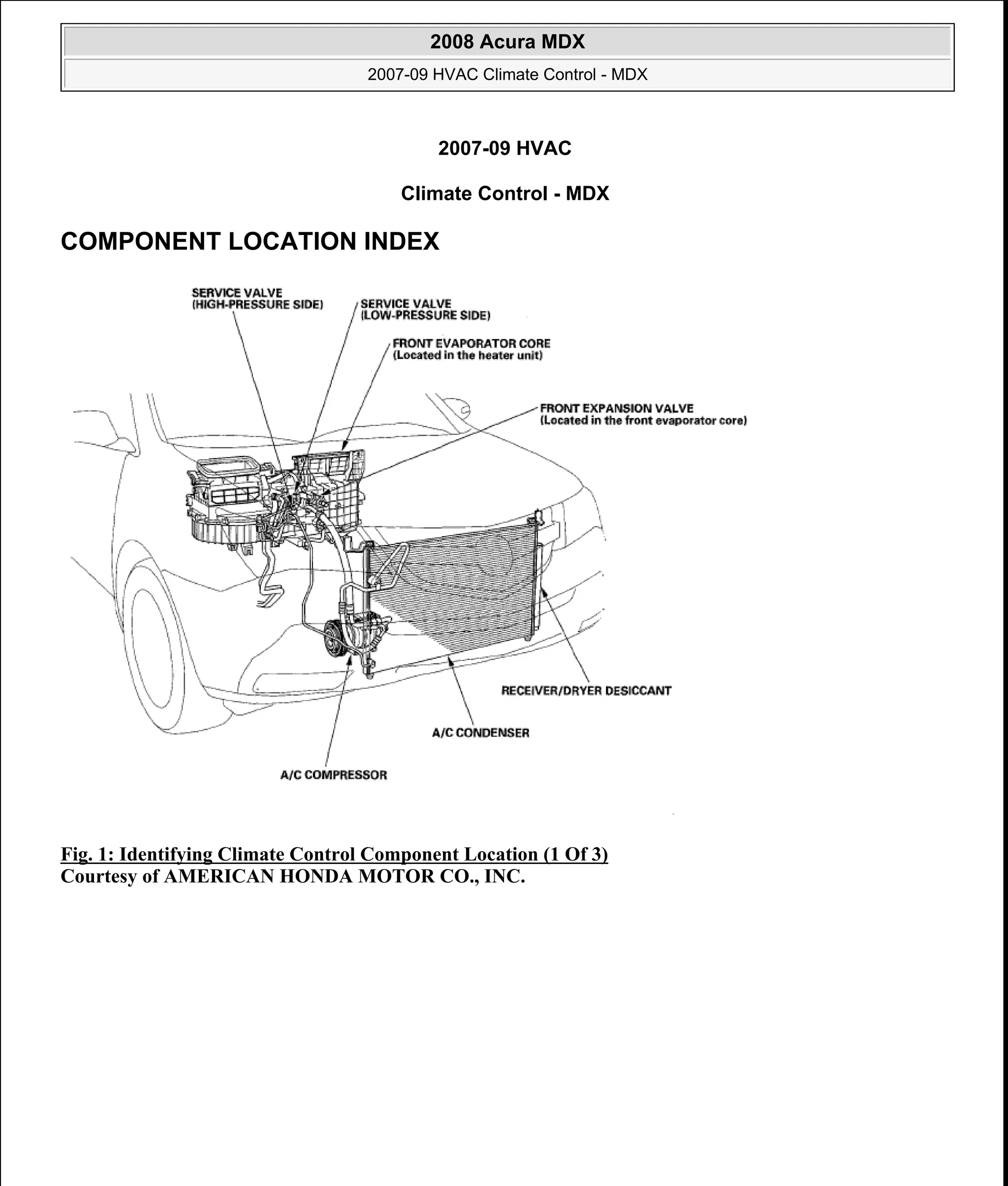
The 2007 Acura MDX utilizes a sophisticated electrical distribution architecture centered around two primary fuse and relay boxes: the under-hood relay box and the interior driver’s side fuse/relay panel. These components act as the central nervous system for the vehicle’s electronics, managing power flow to critical systems such as the fuel pump, cooling fans, powertrain control module (PCM), and lighting arrays. Understanding the layout of these relays is essential for diagnosing intermittent electrical failures, non-starting conditions, or auxiliary system malfunctions.
Understanding the Electrical Architecture of the 2007 Acura MDX
The 2007 model year marked the beginning of the second generation of the Acura MDX. This transition brought significant changes to the electronic control units and the wiring harness layout compared to the first generation. The vehicle relies on a network of relays—electrically operated switches—to allow a low-current signal from the ignition switch or a control module to energize a high-current circuit, such as the starter motor or radiator fan.
In this vehicle, relays are housed primarily in two locations to protect them from environmental debris while maintaining accessibility for servicing. The under-hood relay box, located on the passenger side near the firewall, typically handles high-amperage components that require heavy-gauge wiring for operation. The interior fuse box, located beneath the dashboard on the driver’s side, manages lower-amperage cabin functions, including climate control, interior lighting, and communication modules.
Locating the Under-Hood Relay Box
The under-hood relay box is the primary hub for powertrain-related electrical management. To access this unit:
- Preparation: Ensure the ignition is switched to the OFF position and the parking brake is engaged. Open the hood and locate the black plastic cover on the passenger side near the cowl.
- Access: Depress the locking tabs on the side of the cover to lift it vertically. Avoid using metal screwdrivers to pry the cover, as the plastic tabs can become brittle due to engine heat exposure over the years.
- Identification: The underside of the cover contains a molded diagram identifying the relay and fuse positions. This legend is your most reliable reference for the specific configuration of your vehicle trim level.
It is critical to note that the 2007 Acura MDX may have minor variations in relay configuration depending on whether the vehicle is equipped with the Technology Package or the Sport Package. Always cross-reference the plastic cover diagram with your owner’s manual, as aftermarket accessories or previous repairs may have altered the original layout.
Interior Driver’s Side Fuse and Relay Panel
The interior panel is situated under the dashboard to the left of the steering column. This location is often cramped, making the use of a flashlight and a dedicated fuse puller tool advisable. This panel is responsible for the "body" electronics of the vehicle.
While many of the functions in this area are managed by solid-state fuses, several mechanical relays are embedded in the module to control auxiliary systems like the power windows, windshield wipers, and accessory power sockets. If you are experiencing a failure in one of these cabin systems, the interior panel should be the first point of inspection after confirming that the corresponding fuse is intact.
Relay Troubleshooting and Diagnostics
When an electrical system stops functioning—such as the air conditioning compressor not engaging or the fuel pump failing to prime—the relay is often the primary suspect. Unlike a fuse, which permanently breaks when overloaded, a relay can fail through contact pitting, coil burnout, or mechanical binding.
1. The Audible Test
With the ignition in the ON position, have an assistant trigger the component (e.g., press the AC button). Listen for an audible "click" from the relay box. If you hear the click but the component does not activate, the relay coil is likely receiving power, but the contact points inside the relay may be burnt or stuck.
2. The Swap Test
A quick, non-invasive method for verifying a faulty relay is to swap it with an identical relay from a non-essential circuit. For example, if you suspect the Horn Relay is faulty, swap it with a relay of the same part number from a less critical system. If the horn begins to function, you have confirmed the relay failure. Caution: Only swap relays if they share the exact same part number and pin configuration. Using an incorrect relay can result in a short circuit and damage to the control module.
3. Multimeter Testing
For a definitive diagnosis, remove the relay and use a digital multimeter.
- Coil Resistance: Measure the resistance across the coil pins (usually pins 85 and 86). A standard reading is typically between 60 and 100 ohms, though this varies. An "open" reading (infinite resistance) indicates a burnt-out coil.
- Contact Continuity: Apply 12V power to the coil pins and listen for a click. While energized, the switch pins (typically 30 and 87) should show zero resistance (continuity). If the circuit remains open despite the click, the internal contacts have failed.
Comparison Table: Relay Failure Symptoms
| Component | Potential Symptom | Relay Location |
|---|---|---|
| Fuel Pump Relay | Engine cranks but will not start | Under-hood |
| AC Compressor Relay | AC blows warm air; clutch won't engage | Under-hood |
| Horn Relay | Horn does not sound; fuse is intact | Under-hood |
| Cooling Fan Relay | Engine temperature rises at idle | Under-hood |
| Accessory Power Relay | 12V sockets do not provide power | Interior panel |
Common Maintenance Mistakes
One of the most frequent errors encountered by DIY mechanics involves the "forcing" of relays. Relays are designed to slide into their sockets with minimal resistance. If a relay does not seat properly, do not use excessive force, as this can bend the pin receptacles inside the housing, creating a loose connection that causes intermittent system failure.
Another common oversight is failing to check the grounding points. A relay requires a solid ground to energize the electromagnetic coil. If the chassis ground near the engine bay is corroded, no relay in that box will function correctly, even if the relays themselves are new. Always inspect the wiring harness for signs of fraying or corrosion before replacing components.
Safety Precautions and Limitations
The electrical system of the 2007 Acura MDX is sensitive to voltage spikes. Always disconnect the negative battery terminal before performing major electrical work or replacing any high-current relays. This prevents accidental short circuits that could trigger an airbag warning light or damage the onboard computer (PCM).
Furthermore, avoid "bridging" or bypassing relay pins with jumper wires. While this is a common technique for field testing, it bypasses the safety circuit provided by the relay. A direct jump can lead to overheating of the wires, melted insulation, and a significant risk of vehicle fire. If you are not comfortable using a multimeter to test for voltage and continuity, consult a certified automotive technician, particularly when dealing with the powertrain or fuel system.
When to Seek Professional Assistance
If you have confirmed that the relay is functional and the fuses are intact, yet the component remains inoperative, the issue likely resides in the wiring harness or the control module itself. Diagnostics involving the Controller Area Network (CAN bus) or PCM programming require specialized diagnostic scanners that can "command" specific components to turn on or off.
At this stage, attempting further repairs without the proper schematic wiring diagrams and diagnostic software can lead to "parts cannon" syndrome, where healthy components are replaced at great expense without resolving the underlying electrical fault. A technician can perform a voltage drop test, which identifies hidden resistance in a circuit caused by hidden corrosion or wire damage that is otherwise invisible to a standard multimeter.
Frequently Asked Questions
How can I identify which relay is for the fuel pump? The fuel pump relay is located in the under-hood relay box. Refer to the diagram printed on the underside of the plastic cover. Usually, the relay is labeled with a fuel pump icon or the abbreviation "FP" or "FUEL PUMP."
Are all relays in the 2007 MDX interchangeable? No. While many relays may appear identical externally, they have different internal circuitry. Some include internal resistors or diodes to suppress voltage spikes. Always use the exact Acura-specified part number to ensure compatibility.
What causes a relay to click rapidly? Rapid clicking, often described as a "chattering" sound, usually indicates low voltage. This is frequently caused by a weak battery or a poor connection at the battery terminals, which causes the relay to engage and disengage repeatedly as the voltage fluctuates.
Can I use a relay from a different car model? It is strongly discouraged. Different manufacturers use different internal wiring and trigger voltages. Using an incompatible relay can cause permanent damage to your vehicle's engine control unit.
Where can I find the official wiring diagram for my specific trim? The official Acura Service Manual, available through Helm Inc. or subscription-based online automotive repair databases, is the only source for accurate, vehicle-specific wiring diagrams that account for all trim-level variations.
Final Next Actions
If you are troubleshooting a specific electrical fault in your 2007 Acura MDX, start by checking the under-hood relay box cover legend to verify the location of the suspect relay. Perform the "Audible Test" first to save time. If the relay is non-responsive, swap it with an identical, verified-functional unit from a non-essential circuit. If the problem persists or follows the relay, you can then move on to testing the wiring or seeking professional diagnostic assistance. Maintaining a clean, dry relay box environment is key to preventing future electrical issues.