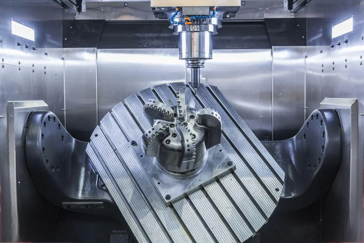
A 5-axis CNC laser cutting machine is an advanced industrial fabrication system that manipulates a high-power laser beam across three linear axes (X, Y, Z) and two rotational axes (typically A/B or B/C). This multi-axis articulation enables non-contact, high-precision cutting, trimming, slotting, and beveling on complex three-dimensional contoured metal and composite parts without requiring multiple setups or manual part repositioning.
Understanding 5-Axis Motion Kinematics in Laser Cutting
Conventional flatbed laser cutters operate on three Cartesian axes: X (longitudinal), Y (transverse), and Z (vertical height). While 3-axis systems excel at processing flat sheet metal and simple profiles, they cannot maintain a perpendicular beam angle against curved, formed, or hydroformed components.
A 5-axis CNC laser cutting machine overcomes this spatial limitation by incorporating two rotational axes into the motion architecture. These additional axes allow the laser cutting head—or, in select machine designs, the workpiece fixture—to tip and rotate in real time.
- Linear Motion
- X Axis: Longitudinal
- Y Axis: Transverse
- Z Axis: Vertical Height
- Rotational Motion
- A Axis: Rotation around X
- B Axis: Rotation around Y
- C Axis: Rotation around Z
The Role of Linear Axes (X, Y, Z)
- X-Axis: Controls the primary longitudinal travel along the machine bed or gantry length.
- Y-Axis: Manages transverse movement across the width of the processing zone.
- Z-Axis: Adjusts vertical elevation, allowing the laser head to accommodate tall 3D structures and move up or down along deep contours.
The Role of Rotational Axes (A, B, C)
The specific rotational configuration depends on the kinematic mechanical design:
- Articulated Head Architecture (B/C or A/B): The laser processing head contains integrated rotary drives. For example, a B-axis swivels the head around the Y-axis (tilt), while a C-axis rotates the head around the Z-axis (pan). This design keeps the workpiece stationary while the laser head moves around it, making it ideal for large, heavy components such as automotive body frames.
- Hybrid/Trunnion Architecture: The laser head handles one or two axes of movement while a rotary table or trunnion fixture rotates the workpiece. This approach offers extreme mechanical rigidity for smaller, high-precision aerospace or medical components.
Vector Alignment and Maintaining Surface Normals
The primary physical objective of 5-axis kinematic control in laser cutting is maintaining the surface normal vector. To deliver optimal optical energy and uniform kerf width, the laser beam must strike the metal surface at a precise 90-degree angle (or a specific programmed angle during bevel cutting).
When cutting a 3D stamped component, the CNC controller continuously calculates the surface geometry and adjusts all five axes simultaneously. This dynamic positioning ensures that the focal point stays situated at a constant distance and orientation relative to the material surface throughout the cutting stroke.
Core Technical Components of 5-Axis CNC Laser Systems
A 5-axis CNC laser machine integrates high-power optics, precision motion controls, real-time sensing feedback, and automated beam delivery.
| Laser Source | Motion & Optics | Control & Sensing |
|---|---|---|
| • Fiber Laser• CO2 Laser• Beam Delivery | • Articulated Head• Dynamic Motors• Rotary Drives | • Multi-Axis CNC• Capacitive Sensor• CAD/CAM Offline Engine |
Fiber Laser vs. CO2 Laser Generators
Modern industrial 5-axis laser cutting machinery predominantly uses fiber laser sources, though high-power CO2 systems remain in specialized service.
- Fiber Lasers: Generate laser light via optical fibers doped with rare-earth elements (such as ytterbium) operating at a wavelength of approximately 1.06 µm. Fiber lasers offer higher wall-plug electrical efficiency (often exceeding 35–40%), minimal maintenance due to solid-state design, and high absorption rates in reflective metals like aluminum, brass, and copper. Beam delivery is handled via flexible fiber-optic cables routed directly through the articulated wrist of the 5-axis head.
- CO2 Lasers: Operate at a 10.6 µm wavelength. Because CO2 laser beams cannot travel through standard optical fibers, they require complex articulated mirror arms (flying optics) with pressurized beam paths to transport light to a 5-axis head. This increases mechanical complexity and maintenance requirements, making fiber lasers the industry standard for new multi-axis installations.
High-Dynamic Articulated Processing Heads
The processing head houses collimation optics, focusing lenses, protective cover slides, assist gas delivery nozzles, and dynamic rotary drives. Due to the high accelerations required when traversing complex 3D paths, 5-axis heads are engineered to maximize torque-to-weight ratios. Direct-drive torque motors are often used in the rotary joints to eliminate gear backlash, delivering high angular resolution and rapid responsiveness during tight contouring.
Capacitive Height Sensing and Focal Control
Maintaining the correct focus position relative to the workpiece is critical for consistent cut quality. 5-axis laser heads feature high-speed capacitive height sensors built directly into the nozzle assembly.
These sensors measure capacitance variations between the conductive nozzle tip and the metallic workpiece in real time. If a stamped part exhibits heat deformation, springback, or manufacturing tolerances, the CNC controller instantly adjusts the Z-axis offset and head orientation to prevent physical nozzle collisions while holding the focus position within micrometers.
Multi-Axis CNC Controllers & CAD/CAM Integration
Controlling five interpolating axes simultaneously requires significant computational power. Advanced CNC controllers process complex algorithms to execute smooth Tool Center Point (TCP) management. TCP control allows programmers to define feed rates at the point where the laser beam intersects the material, regardless of how much the head rotates or pivots above it.
Offline 3D CAD/CAM programming software is essential for 5-axis laser processing. Software packages simulate toolpaths, generate multi-axis motion code, automatically calculate beam normal vectors, and perform full 3D collision avoidance checks against machine structure, clamping fixtures, and raw workpieces.
Primary Applications Across Manufacturing Sectors
5-axis CNC laser cutting technology is utilized in industries that fabricate complex, high-strength 3D sheet metal, hydroformed tubes, and structural enclosures.
- Automotive
- Hot-stamped steel
- Hydroformed tubes
- Body-in-white panels
- Aerospace
- Turbine casings
- Ducting & baffles
- Titanium shielding
- Energy & Medical
- Orthopedic implants
- Turbine combustion
- Custom enclosures
Automotive Industry: Hot-Stamped and Hydroformed Components
The automotive sector represents the largest market for 5-axis laser cutting systems. The adoption of high-strength, hot-stamped boron steels (such as 22MnB5) for vehicle safety cages, A-pillars, B-pillars, and bumper beams presented challenges for traditional mechanical trimming dies, which wear rapidly when blanking hardened steels (exceeding 1,500 MPa tensile strength).
5-axis laser cutting allows automakers to trim 3D hot-stamped parts and pierce mounting holes after press-hardening without physical tool wear. Additionally, hydroformed tubular frame components—which feature varying spatial cross-sections—are trimmed and slotted on 5-axis laser work cells in a single process step.
Aerospace: Sheet Metal Enclosures and Engine Ducting
Aerospace manufacturing relies heavily on lightweight contoured sheet metal parts made from titanium alloys, Inconel, stainless steel, and aluminum. 5-axis lasers cut complex patterns, air intake baffles, exhaust ducting, and structural skins without introducing mechanical deformation or stress concentrations.
Structural Tubing and Deep-Drawn Parts
Beyond flat-sheet converting, 5-axis systems handle curved structural tubes, agricultural machinery brackets, deep-drawn appliance panels, and custom stainless steel enclosures. The ability to trim drawn edges, cut internal cutouts, and bevel thick tube walls in a single clamping operation streamlines low-to-medium volume fabrication.
5-Axis vs. 3-Axis Laser Cutting: Key Differences and Advantages
Understanding when to select 5-axis motion over traditional 3-axis flatbed processing depends on part geometry, production volume, and secondary processing needs.
- 3-Axis Cutting
- Flat sheet metal processing
- Fixed perpendicular beam
- High-volume flat blanking
- Minimal setup, simple code
- 5-Axis Cutting
- 3D contoured, formed metal
- Articulated normal vector
- Weld prep & edge beveling
- Complex 3D CAD/CAM offline
1. Geometric Versatility
- 3-Axis Systems: Limited to 2D flat sheets, plates, or simple rotational tubing with dedicated rotary attachments. They cannot cut perpendicular features on pre-formed 3D surfaces.
- 5-Axis Systems: Process fully formed, deep-drawn, stamped, or hydroformed 3D parts. They reach compound angles, internal pocket features, and complex spatial curves across multiple planes.
2. Elimination of Hard Mechanical Trimming Dies
In high-volume automotive production, secondary trimming was historically performed using heavy stamping dies. Designing, machining, and maintaining these mechanical dies requires significant capital and long lead times.
5-axis laser cutting replaces hard tooling with flexible software programming. When a part design changes, engineers update the CAD model and re-generate the laser toolpath, avoiding costly die re-tooling.
3. Edge Quality, Beveling, and Weld Preparation
To prepare thick-walled parts for welding, edges often require bevel angles (V-grooves, Y-grooves, or chamfers). A 3-axis laser can only make straight vertical cuts. A 5-axis laser head can tilt up to ±135 degrees (depending on kinematic limits) to execute precision bevel cuts during the primary trimming pass, eliminating secondary mechanical grinding or milling.
4. Consolidated Fixturing and Reduced Setup Cycles
Processing a contoured component using traditional 3-axis equipment or manual trimming often requires multiple operations, repositioning steps, and custom fixtures. A 5-axis system processes all sides, cutouts, trim lines, and hole profiles in a single automated fixture clamp cycle, reducing cumulative position errors.
Technical Comparison Matrix
The following matrix compares primary functional characteristics across common industrial laser cutting configurations:
| Feature / Metric | 3-Axis Flatbed Laser | 3-Axis Laser with Rotary Axis | 5-Axis 3D Laser Cutting System |
|---|---|---|---|
| Primary Motion | X, Y, Z (Linear) | X, Y, Z + Rotary Axis (A or C) | X, Y, Z + Rotary A/B/C Axes (Interpolated) |
| Workpiece Type | Flat sheets, plates | Cylindrical/Square straight pipes | Formed 3D stampings, hydroformed tubes, deep-drawn parts |
| Laser Focal Orientation | Fixed 90° to machine table | Fixed 90° relative to tube axis | Dynamic variable vector (maintains normal angle to 3D curves) |
| Bevel Cutting Capability | No | Limited (rotary indexing only) | Yes (full dynamic angle beveling up to ±135°) |
| Programming Complexity | Low (2D CAD/CAM) | Moderate (2.5D/3D pipe software) | High (Full 3D kinematic simulation & collision detection) |
| Fixturing Requirements | Flat slats / pin tables | Chucks, steady rests, rollers | Custom 3D support fixtures / vacuum / hydraulic clamping |
| Typical Capital Cost Range | Lower ($150k - $600k+) | Moderate ($250k - $750k+) | High ($600k - $2.5M+) |
Key Operating Parameters and Machine Specifications
Achieving optimal throughput and edge quality on a 5-axis CNC laser system requires precise control over several key technical parameters.
- Laser Power
- 2kW to 15kW+ Fiber
- Wavelength (~1.06µm)
- Beam Parameter Prod.
- Motion Dynamics
- Acceleration (1-2G)
- TCP Velocity
- Rotary Speeds (°/s)
- Assist Gas
- Nitrogen (Clean cut)
- Oxygen (Exothermic)
- Compressed Air
Laser Power and Thickness Capacities
- 2 kW – 4 kW Fiber Lasers: Ideal for thin-gauge automotive stampings (0.7 mm to 2.5 mm), offering high cutting speeds and narrow heat-affected zones (HAZ).
- 6 kW – 10 kW Fiber Lasers: Used for medium-thickness structural elements, high-strength alloy trimming, and faster processing of complex spatial profiles.
- 12 kW – 20 kW+ Fiber Lasers: Selected for heavy structural steel tube profiling, thick bevel cutting, and high-speed industrial processing.
Motion Dynamics and Acceleration Rates
Because 3D laser trimming involves rapidly changing directions along complex radii, machine acceleration is a critical factor in cycle time. Modern 5-axis gantries feature linear motor drives on primary axes capable of accelerations ranging from 1.0 G to over 2.0 G, with rotary axis speeds exceeding several hundred degrees per second. High dynamics ensure the machine maintains its target feed rate along tight corners, preventing localized burning or thermal warping.
Assist Gas Options and Cutting Physics
The assist gas is blown coaxially through the cutting nozzle along with the focused laser beam to purge molten metal from the kerf.
- Laser Focus Head
- Assist Gas In
- Coaxial Nozzle
- Laser Beam and Assist Gas Jet directed into Melt Zone (Kerf) on Workpiece 3D
- Nitrogen ($N_2$): Performs high-pressure inert fusion cutting (typically 10 to 20+ bar). It prevents oxidation, leaving a bright, clean, weld-ready edge. This is the primary choice for stainless steel, aluminum, and automotive body parts.
- Oxygen ($O_2$): Facilitates reactive exothermic cutting at lower pressures (0.5 to 5 bar). The chemical reaction between oxygen and carbon steel generates extra heat, allowing lower laser power levels to cut thicker mild steel, though an oxide layer is left on the cut edge.
- High-Pressure Compressed Air: Serves as a cost-effective alternative for thin mild steel and aluminum, using a mix of nitrogen and oxygen to maximize processing speeds while lowering operating gas expenses.
Volumetric Positional Accuracy and Calibration
Because 5-axis systems operate across five interpolating axes, volumetric positioning errors can accumulate. Advanced machines utilize optical glass scales, absolute rotary encoders, and automated laser tracker calibration systems. High-end systems feature automated beam-centering routines, where the machine periodically fires into a calibration target to automatically measure and correct any mechanical drift in the laser head.
Cost Analysis, Maintenance, and ROI Considerations
Investing in a 5-axis CNC laser cutting system requires balancing initial capital costs against operational efficiency and long-term production flexibility.
- CAPEX Breakdown
- Machine Tool Base & Gantry
- Laser Source Generator
- CAD/CAM Software Licensing
- Custom 3D Tooling/Fixtures
- OPEX Factors
- Assist Gas Consumption
- Optical Consumables
- Electrical Utility Power
- Operator & Programmer Skill
Capital Expenditure (CAPEX) vs. Tooling Savings
While a 5-axis laser cutting machine carries a higher upfront capital investment than a standard flatbed unit, it can significantly lower tooling costs in high-mix or evolving production environments. By eliminating progressive stamping dies, hard trimming fixtures, and manual deburring operations, manufacturers can reduce time-to-market for new part designs from months to days.
Operating Expenditure (OPEX) Components
- Assist Gas Expenses: Nitrogen gas consumption during high-pressure fusion cutting represents a major portion of operational costs. Facility planning often requires liquid nitrogen bulk storage tanks or on-site high-pressure nitrogen generation systems to manage costs.
- Optical Consumables: Protective cover slides, copper nozzles, and ceramic isolators are subject to spatter and contamination. Standard preventive maintenance schedules require daily inspection and cleaning of protective optics.
- Power Consumption: Fiber laser systems feature lower electrical footprints than older CO2 units, but high-pressure chillers, dust extractors, and multi-axis servo drives still require robust electrical infrastructure.
Preventive Maintenance Requirements
To preserve sub-millimeter positional repeatability, 5-axis laser machines require structured maintenance routines:
- Daily/Weekly: Clean and inspect nozzle tips; inspect protective optical cover slides; check assist gas supply pressures; clean dust collector filters.
- Monthly/Quarterly: Verify Z-axis capacitive sensor calibration; inspect dynamic cover bellows for tears; check axis lubricant levels and linear guides.
- Bi-Annually/Annually: Perform full laser beam quality and power meter checks; execute 5-axis TCP volumetric alignment using dynamic laser measurement tools; refresh laser chiller coolant and internal deionizing filters.
Frequently Asked Questions
What is the main structural difference between a 5-axis CNC router and a 5-axis CNC laser machine?
A 5-axis CNC router uses a high-speed mechanical spindle driving a rotating physical cutting tool (such as an end mill) to chip material away, generating significant physical cutting forces that require heavy, rigid machine bases and mechanical workholding. A 5-axis laser cutting system uses a focused beam of coherent light to melt or vaporize material without physical contact. This non-contact process eliminates mechanical tool thrust forces, allowing for rapid accelerations and minimal mechanical clamping pressures on fragile thin-walled components.
How does capacitive focal control handle hot-stamped parts with variable springback?
The 5-axis laser cutting head incorporates a high-speed capacitive distance sensor built directly into the copper nozzle tip. As the laser tracks along a contoured metal component, the sensor continuously measures changes in electrical capacitance between the nozzle and the workpiece surface. If the stamped metal part flexes or deviates due to springback or thermal stress, the controller adjusts the Z-axis linear position and head orientation in milliseconds, holding the programmed focal point and standoff distance constant to protect the nozzle and maintain edge quality.
Can a 5-axis CNC laser cut bevel angles for structural welding preparation?
Yes. By interpolating the A, B, or C rotary axes while traversing a linear cutting line, a 5-axis laser system can tip the processing head relative to the metal edge. This allows the machine to perform V-bevels, Y-bevels, chamfers, and variable-angle transitions along curved 3D geometries, creating precision joint prep profiles for automated robotic welding without requiring secondary mechanical edge grinding.
Why are fiber laser sources preferred over CO2 lasers in 5-axis cutting applications?
Fiber lasers deliver their beam through flexible fiber-optic cables that can be easily routed through the dynamic joint articulated arm of a multi-axis gantry. CO2 lasers generate a light wavelength (10.6 µm) that cannot travel through standard optical fibers, requiring a complex series of pressurized beam delivery tubes, turning mirrors, and bellows systems that add weight, alignment sensitivity, and maintenance overhead to a 5-axis moving head. Fiber lasers also offer higher electrical efficiency and process reflective metals like aluminum and brass more effectively.
What skill sets are required to program and operate a 5-axis laser system?
Programming a 5-axis laser cutting system requires expertise in 3D CAD/CAM software environments. Programmers must understand vector math, spatial toolpath optimization, surface normal calculations, collision avoidance, dynamic acceleration limits, and assist gas selection. Machine operators require training in optical inspection, capacitive sensor calibration, focal alignment procedures, and safe light-containment safety protocols (Class 1 enclosure operations).
Strategic Evaluation and Implementation Strategy
Implementing 5-axis CNC laser cutting technology requires a structured approach to ensure optimal operational integration and return on investment:
- Conduct Part Geometry and Tolerance Audits: Identify whether existing or upcoming components feature true spatial contours, deep draw features, compound bevels, or variable normal angles that justify multi-axis articulated processing over 3-axis cutting or hard stamping dies.
- Evaluate Material and Thickness Profiles: Determine required fiber laser wattage based on material types (e.g., hot-stamped boron steel, aluminum, titanium alloys) and maximum wall thicknesses to balance cutting speed against power consumption.
- Analyze Assist Gas Infrastructure: Assess on-site nitrogen generation or bulk liquid supply facilities to support high-pressure fusion cutting requirements continuously.
- Select CAD/CAM Software and Simulation Workflows: Ensure your team adopts 3D CAM software featuring accurate 3D machine kinematics, automatic TCP toolpath generation, dynamic orientation smoothing, and robust collision detection.
- Establish Safety and Enclosure Compliance: Verify that the laser system operates within a fully light-tight enclosure meeting Class 1 safety standards, equipped with interlocked doors, laser-rated safety glass, and high-efficiency particulate air (HEPA) dust extraction systems.