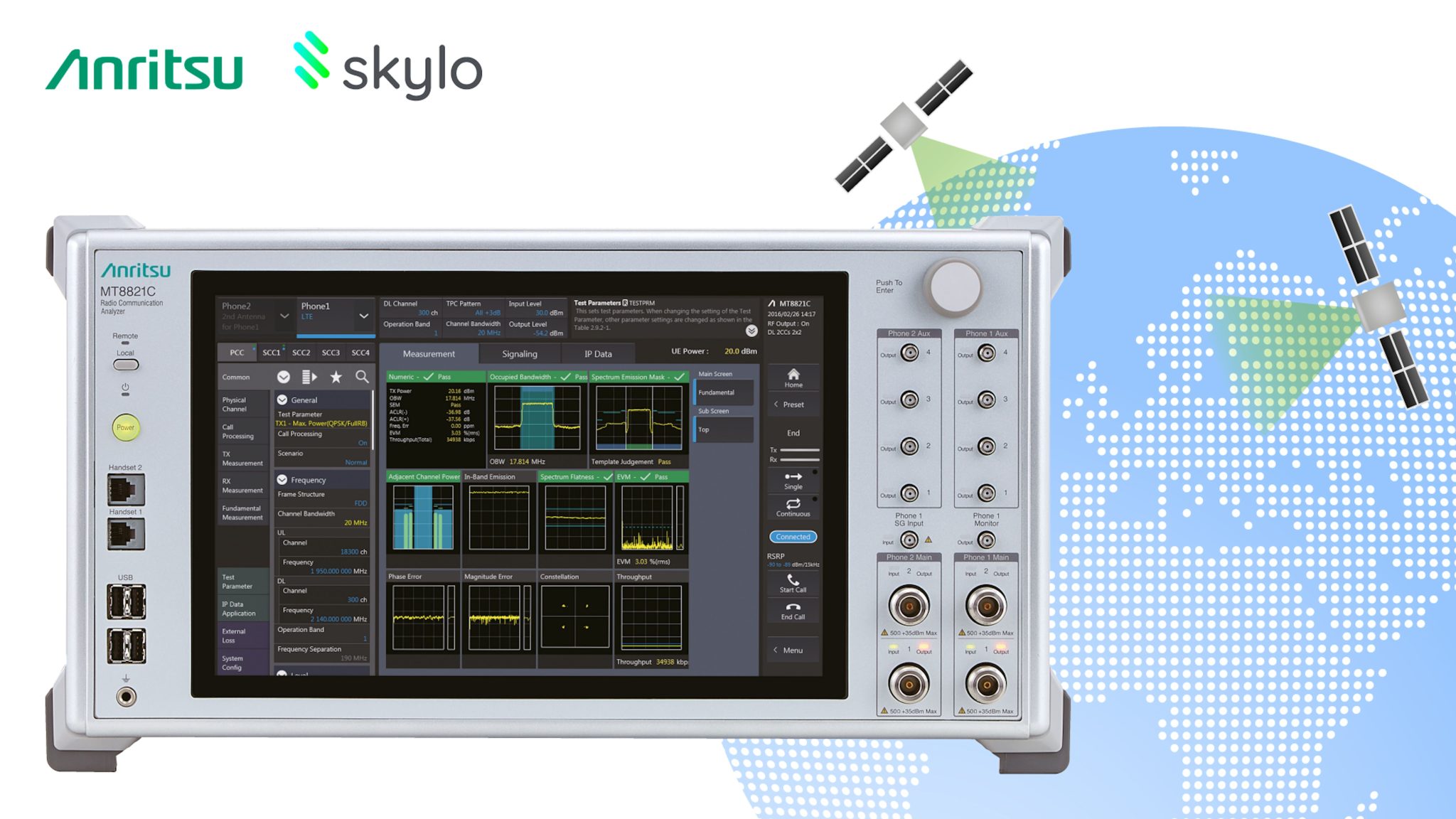
Anritsu Corporation is a global leader in electronic test and measurement solutions, providing specialized hardware, software, and integrated systems for telecommunications, optical networking, radio frequency (RF), and semiconductor testing. Its equipment enables engineers, network operators, and manufacturers to design, validate, deploy, and maintain high-speed wireless networks, fiber-optic infrastructure, and electronic components worldwide.
Historical Evolution and Corporate Overview of Anritsu
Founded in Japan in 1895, Anritsu Corporation began as Sekisan-sha before evolving through pivotal mergers, including the integration of Annaka Electric Works and Kisha Seizo. The company played an early role in establishing Japan’s public wire and wireless communications infrastructure. Over the past century, Anritsu transformed from a pioneer in public telephony and radio transmitters into an international test and measurement (T&M) technology leader.
Headquartered in Atsugi, Kanagawa Prefecture, Japan, Anritsu operates development, manufacturing, and support centers across North America, Europe, and Asia-Pacific. While the corporation maintains specialized divisions in industrial automation—such as X-ray inspection and checkweighing equipment for food and pharmaceutical packaging through Anritsu Infivis—its primary core domain remains electronic test equipment.
The Test & Measurement division targets the full life cycle of communication systems. This lifecycle spans initial research and development (R&D) in semiconductor foundries and standards labs to volume manufacturing, conformance verification, base station installation, and long-term network maintenance. Anritsu’s strategic positioning relies on anticipating architectural shifts in telecommunication standards, such as the migration from legacy 3G/4G to 5G New Radio (NR) and emerging 6G research, as well as the transition from NRZ signaling to PAM4 modulation in optical data centers.
Core Domains of Anritsu Test & Measurement Equipment
Anritsu designs electronic test equipment tailored to technical challenges across several main domains: cellular wireless, high-speed digital interconnects, optical transport, RF/microwave, and field operation.
Anritsu Test Equipment Ecosystem:
- Wireless & 5G/6G (MT8000A, etc.)
- Optical & BERT (MP1900A, OTDR)
- RF & Microwave (VNAs, Spectrum)
- Field Testing (Field Master)
Wireless Communications and Cellular Protocol Testing
In mobile communications, Anritsu provides instrumentation that simulates base stations and user equipment (UE) across the protocol stack. The company’s test platforms cover Physical Layer (PHY) RF characterization, Protocol Stack testing, and Radio Resource Management (RRM).
Key capabilities in this domain include:
- 5G NR signaling and non-signaling test setups: Supporting Sub-6 GHz (FR1) and millimeter-wave (FR2) frequency bands.
- Over-the-Air (OTA) testing: Integration with compact antenna test ranges (CATR) and anechoic chambers to measure beamforming accuracy, Equivalent Isotropically Radiated Power (EIRP), and total radiated sensitivity.
- Carrier Aggregation and MIMO evaluation: Validating throughput performance under complex multi-carrier configurations and spatial multiplexing scenarios.
- Conformance and carrier acceptance testing: Providing test suites accredited by certification bodies such as GCF (Global Certification Forum) and PTCRB.
Optical Interconnects and Transport Testing
As data centers and telecommunication backhauls scale to handle exponential traffic growth, Anritsu supplies high-speed bit error rate testers (BERT), optical spectrum analyzers (OSA), and optical time-domain reflectometers (OTDR).
Modern data center interconnects rely on PAM4 (4-level Pulse Amplitude Modulation) at 56 Baud and 112 Baud per lane to achieve 400GbE, 800GbE, and 1.6TbE throughput rates. Anritsu optical test platforms generate low-jitter, highly precise signal patterns to evaluate receiver jitter tolerance, Forward Error Correction (FEC) symbol error ratios, and signal degradation over single-mode and multi-mode fiber spans.
RF, Microwave, and Millimeter-Wave Instrumentation
Anritsu produces benchtop and modular instruments for measuring fundamental high-frequency electromagnetic characteristics:
- Vector Network Analyzers (VNAs): Measuring complex S-parameters ($S_{11}, S_{21}, S_{12}, S_{22}$) to characterize impedance matching, gain, insertion loss, and phase behavior of filters, amplifiers, antennas, and transmission lines up to sub-THz frequencies.
- Spectrum and Signal Analyzers: Capturing amplitude versus frequency distributions, detecting spurious emissions, and demodulating complex vector signals (such as QAM and OFDM).
- RF Power Meters and Synthesized Signal Generators: Delivering calibrated RF power reference levels and ultra-clean local oscillator signals with low phase noise.
Field Testing and Network Installation
Field operations demand rugged, lightweight, battery-powered instrumentation capable of operating in harsh outdoor environments. Anritsu pioneered handheld field analyzers with integrated cable and antenna analyzers (Site Master series), spectrum analyzers (Field Master series), and optical network testers (Network Master series).
Field engineers use these portable units to locate transmission line impedance mismatches (via Distance-to-Fault measurements), trace co-channel RF interference, audit base station antenna coverage, and certify fiber optic cabling during initial site turn-up.
Detailed Comparison of Key Anritsu Test Equipment Platforms
The following matrix provides a technical overview of flagship Anritsu equipment series, detailing their architecture, frequency/data limits, primary applications, and targeted operating environments.
| Equipment Platform / Series | Core Testing Domain | Primary Capabilities & Specifications | Target Applications | Operational Environment |
|---|---|---|---|---|
| Radio Communication Test Station MT8000A | 5G / 6G Wireless Signaling & RF | Covers Sub-6 GHz (FR1) to mmWave (FR2 up to 71 GHz); supports 4x4 MIMO, protocol stack analysis, and RF parametric tests. | 5G NR mobile terminal R&D, chipset validation, GCF/PTCRB conformance, carrier acceptance testing. | Laboratory / R&D Bench & Chamber Setup |
| Signal Quality Analyzer-R MP1900A | High-Speed Digital BERT & Optical | Multichannel BERT supporting NRZ and PAM4 up to 64 Gbaud; integrated PPG, ED, jitter injection, and FEC analysis. | 400G/800G/1.6T optical module characterization, PCIe Gen 5/6, USB4, and serializer/deserializer (SerDes) testing. | Advanced R&D Lab & High-Speed Interface Testing |
| Field Master Pro MS2090A | Handheld RF Spectrum & Field Analysis | Sweep rates up to 54 GHz; 110 MHz real-time spectrum analysis (RTSA) bandwidth; low DANL (Display Average Noise Level). | RF interference hunting, 5G NR field coverage mapping, radar signal analysis, satellite communications audit. | Outdoor Field Maintenance & Tower Sites |
| ShockLine VNA Family (e.g., MS46122B / MS46322B) | Vector Network Analysis | Frequency coverage from 1 MHz up to 43.5 GHz; compact 1U/2U chassis; patented VNA-on-a-chip architecture. | Passive RF component manufacturing (filters, cables, connectors), educational labs, automated test equipment (ATE) racks. | Production Manufacturing & Quality Assurance Labs |
| Network Master Pro MT1000A | Portable Optical Transport & OTDR | All-in-one transport tester from 1.5 Mbps to 100 Gbps; dual-wavelength OTDR modules; CPRI/eCPRI front-haul testing. | Fiber optics characterization, Ethernet service activation, mobile front-haul/backhaul installation, metro network audits. | Telecom Field Operation & Central Office |
Practical Engineering Applications and Industry Impact
Anritsu equipment plays an essential role across multiple technological sectors. Engineers rely on these systems to verify compliance with international standards established by organizations such as 3GPP, IEEE, ITU-T, and PCI-SIG.
Anritsu Industry Application Ecosystem:
- Aerospace, Defense & Space
- Radar characterization
- Satellite comms testing
- Electronic warfare audit
- Semiconductor & Interface
- PCIe Gen 5/6 validation
- SerDes physical layer test
- PAM4 / 800G module testing
- Telecom Installation & Ops
- Base station turn-up
- Interference hunting
- OTDR fiber loss mapping
Aerospace, Defense, and Satellite Communications
In defense and space systems, signal integrity and spectral purity are critical. Anritsu spectrum analyzers and VNAs are widely used to build and verify radar systems, electronic warfare (EW) receiver modules, and satellite ground station transceivers.
- Radar Pulse Analysis: High-bandwidth signal analyzers capture transient pulse signatures, phase linearity, and rise/fall times of X-band, Ku-band, and Ka-band military radar transmissions.
- Satellite Transceiver Alignment: Portable analyzers allow field engineers to measure gain flatness, phase noise, and group delay on satellite uplinks directly at dish feed horns.
Semiconductor Characterization and High-Speed Bus Validation
Semiconductor foundries and fabless chip designers utilize Anritsu bit error rate testers (BERT) and vector network analyzers to characterize high-speed digital transceivers (SerDes).
Before a chipset can receive compliance certification for standards such as PCI Express (PCIe Gen 5/6), USB4, or Thunderbolt, its physical layer must undergo rigorous stress testing. Anritsu MP1900A platforms inject controlled amounts of sinusoidal jitter, random jitter, bounded uncorrelated jitter (BUJ), and crosstalk into the data channel. The system then measures the device’s eye diagram opening, receiver sensitivity limits, and jitter tolerance curves under stressed conditions.
- Stressed Signal Input (Jitter + Noise + ISI)
- Device Under Test (DUT)
- Error Detector / Eye Diagram Analysis (Evaluated by Anritsu MP1900A BERT)
Mobile Network Deployment and Tower Site Maintenance
During wireless network build-outs, installation teams use Anritsu field equipment to ensure antenna systems meet structural and electrical specifications.
A primary cause of dropped calls and degraded throughput in cellular networks is Passive Intermodulation (PIM)—spurious RF signals generated when high-power signals interact with non-linear physical junctions in cabling, corroded connectors, or structural metalwork near antennas. Anritsu PIM Master analyzers send high-power test tones down the transmission line to isolate and locate PIM sources down to the exact distance on a cable run, enabling rapid field remediation.
Operational Guidelines: Selection, Calibration, and Best Practices
To achieve accurate measurement results and maximize the lifespan of Anritsu test equipment, engineering teams should adhere to structured operational procedures.
Equipment Selection Parameters
When selecting Anritsu test instruments for a specific project, evaluate the following technical criteria:
- Frequency Coverage: Ensure the instrument's upper frequency boundary exceeds the highest harmonic required by your measurement standard (e.g., assessing the 3rd or 5th harmonic of a carrier signal).
- Dynamic Range and Noise Floor: For low-level signal detection or high-rejection filter testing, select instruments with a low Displayed Average Noise Level (DANL) or high VNA system dynamic range (>110 dB).
- Real-Time Bandwidth (RTSA): For capturing intermittent interference, frequency-hopping signals, or transient events, select spectrum analyzers with sufficient real-time analysis bandwidth to guarantee a 100% Probability of Intercept (POI).
- Form Factor and Mobility: Benchtop units offer higher port density and precision for R&D, while battery-powered, weather-sealed handheld units are necessary for field environments.
Calibration, Traceability, and Maintenance Procedures
Precision test equipment requires regular calibration against recognized national standards, such as those maintained by NIST (National Institute of Standards and Technology) or NMIJ (National Metrology Institute of Japan).
- Annual Factory Calibration: Schedule annual system-level calibrations with Anritsu service centers or ISO/IEC 17025-accredited calibration laboratories to verify amplitude accuracy, frequency stability, and timebase drift.
- User Calibration (VNA Vector Error Correction): Before taking measurements on a VNA, perform a manual or automatic user calibration (e.g., SOLT: Short-Open-Load-Through, or AutoCal) at the precise reference plane of the Device Under Test (DUT). This process mathematically removes phase shift, insertion loss, and cable reflections introduced by test leads and adapters.
- VNA Port
- Test Cable
- Reference Plane / AutoCal (System Errors Calibrated Out)
- Device Under Test (DUT)
- Connector Care: Torque high-frequency precision RF connectors (3.5 mm, 2.92 mm, 1.85 mm, 1.0 mm) using calibrated torque wrenches. Inspect connector mating faces under magnification to avoid transferring metal debris or center-pin damage to instrument ports.
Automated Test Software Integration
Modern production lines require automated test routines to maintain high throughput. Anritsu instruments support standard SCPI (Standard Commands for Programmable Instruments) command set syntax over Ethernet (LXI), GPIB, or USB interfaces.
Engineers can control Anritsu hardware using automation scripts written in Python, C++, MATLAB, or NI LabVIEW. Utilizing official Anritsu software development kits (SDKs) and IVI drivers reduces development cycles for production automated test equipment (ATE) setups.
Frequently Asked Questions
What is Anritsu Corporation primarily known for in the test equipment industry?
Anritsu Corporation is primarily recognized as a leader in telecommunications, RF, microwave, and optical test instrumentation. It is renowned for introducing the first commercial handheld cable and antenna analyzer (Site Master), pioneer solutions for 5G NR signaling and protocol validation (MT8000A), and high-speed bit error rate testers (MP1900A) used in data center module design.
How does the Anritsu MT8000A support both 5G and early 6G research?
The Anritsu MT8000A Radio Communication Test Station uses a modular baseband architecture that supports non-standalone (NSA) and standalone (SA) 5G NR modes across FR1 (Sub-6 GHz) and FR2 (mmWave) frequencies. By coupling the platform with specialized external up/down converters and extended hardware modules, research teams can expand test frequencies into sub-THz regions required for 6G waveform and protocol exploratory work.
What is the practical difference between benchtop and handheld Anritsu analyzers?
Benchtop Anritsu analyzers (such as high-end signal quality analyzers or bench VNAs) prioritize maximum dynamic range, ultra-low phase noise, high processing throughput, multi-channel capabilities, and modular expansion for laboratory R&D. Handheld units (like the Field Master or Site Master series) prioritize portability, battery endurance, ruggedized IP-rated enclosures, fast startup, and specialized field testing workflows like Distance-to-Fault and outdoor interference hunting.
Why is Bit Error Rate (BERT) testing critical in optical fiber development?
Bit Error Rate testing directly evaluates a system’s ability to transmit digital information without corruption over physical media. As optical channels move to higher data rates using PAM4 multi-level encoding, signal margins become narrower. Anritsu BERT systems inject calibrated jitter and noise into the link to accurately measure receiver error floors, ensuring optical transceivers conform to strict IEEE and OIF standards.
How does Anritsu equipment ensure compliance with international standards?
Anritsu works directly with standards bodies—including 3GPP, IEEE, ITU-T, and PCI-SIG—to develop test software scripts and hardware interfaces that conform precisely to standard specifications. Their equipment software receives regular updates to reflect evolving standard test cases, allowing manufacturers to certify their hardware for global market entry with accredited bodies like GCF and PTCRB.
Practical Recommendations for Test Equipment Procurement and Integration
To implement Anritsu test equipment effectively within your organization's engineering or operational workflow, take the following steps:
- Map Technical Requirements to Instrument Specifications: Define your operating frequency limits, modulation formats, signal levels, and dynamic range requirements before choosing an instrument class. Avoid under-specifying bandwidth limits, as high-speed digital patterns require sufficient harmonic spectrum coverage for clear eye diagram measurements.
- Standardize Calibration and Connector Protocols: Implement strict handling procedures for high-frequency RF connectors and optical interfaces across your facility. Use calibrated torque wrenches for RF adapters and perform fiber end-face inspection/cleaning prior to making optical connections to prevent hardware damage.
- Leverage Software Automation SDKs: For production testing, transition from manual front-panel operations to automated test scripts using Anritsu’s SCPI command libraries and Python drivers. Automation standardizes test procedures, minimizes operator error, and significantly speeds up unit throughput during mass production.
- Establish a Scheduled Calibration Plan: Maintain an up-to-date calibration cycle traceable to national metrological standards. Document user-calibration parameters (such as VNA SOLT calibration files) for lab personnel to ensure test consistency across shifts and locations.