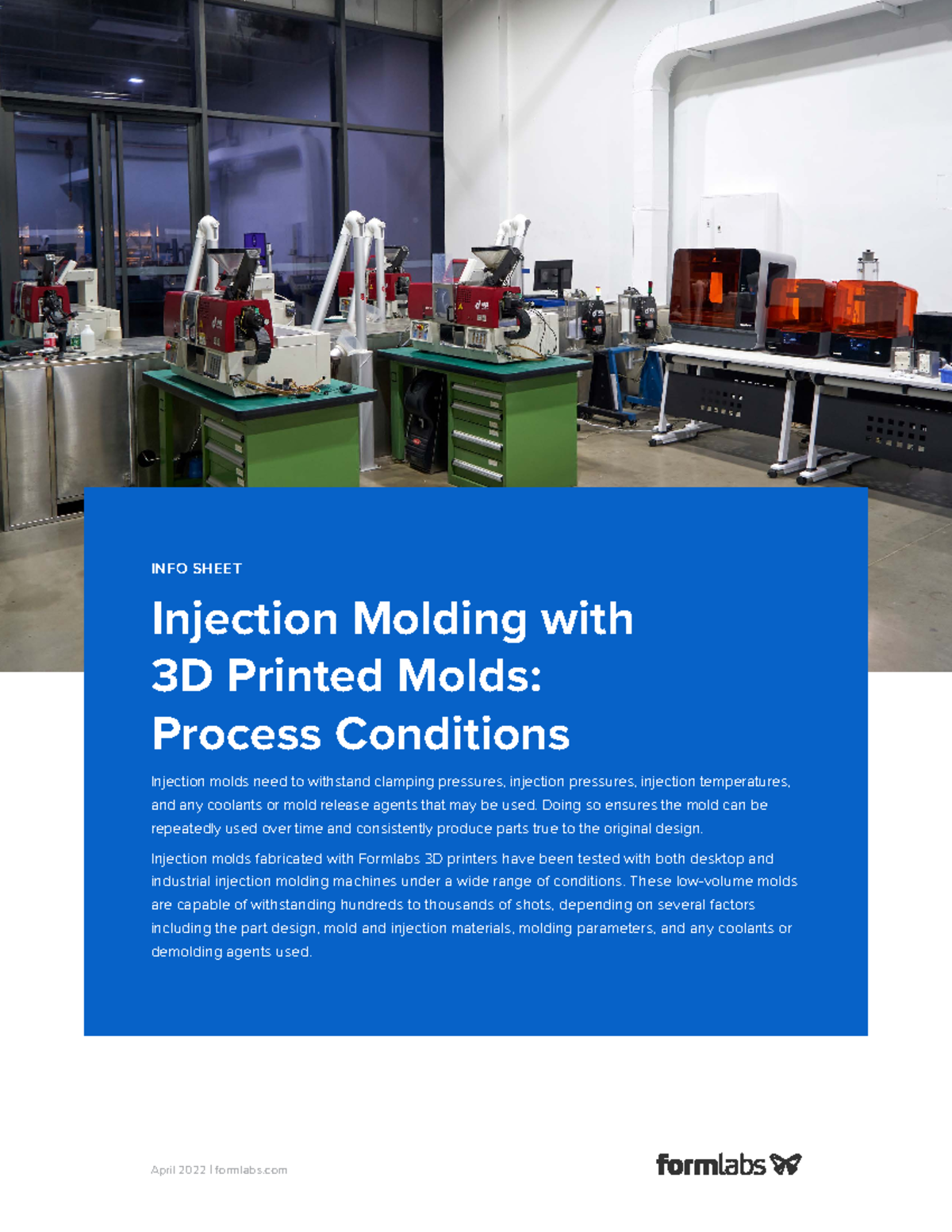
Rapid tooling using additive manufacturing bridges the gap between low-volume prototyping and mass production by drastically reducing lead times and costs, though it requires careful management of thermal stress, polymer selection, and design geometry.
The intersection of additive manufacturing and traditional production methods has unlocked new paradigms for rapid manufacturing, particularly through the use of 3D printed molds for injection molding. For decades, creating traditional metal tooling made from aluminum or P20 tool steel was a mandatory, high-stakes gatekeeper for any plastic component. Cutting metal required weeks—sometimes months—of lead time and thousands of dollars in capital expenditure, rendering it prohibitive for iterative prototyping or low-volume runs. Today, leveraging high-performance 3D printing technologies to produce insert tooling or complete mold halves has transformed the product development lifecycle.
By bypassing traditional Computer Numerical Control (CNC) machining for the mold itself, engineers can iterate complex plastic geometries overnight. However, this workflow is not a simple plug-and-play alternative to steel. Utilizing 3D printed molds introduces a distinct set of thermodynamic, mechanical, and operational challenges that must be navigated to achieve dimensional accuracy and structural integrity. Understanding these dynamics is essential for engineers, product designers, and manufacturers looking to harness the speed of rapid tooling without compromising part quality.
1. Material Selection Dictates Thermal and Mechanical Endurance
The most fundamental constraint when implementing 3D printed molds lies in the raw materials used to build the tool. Unlike traditional metal tooling, which easily withstands extreme clamp tonnage and repeated thermal shock, polymer- or composite-based 3D printed molds operate under significantly tighter physical limits. Selecting the appropriate 3D printing technology and material determines whether a mold will successfully complete a short run of fifty parts or fail catastrophically on the very first shot.
Photopolymers vs. High-Performance Thermoplastics
Stereolithography (SLA) resins are frequently utilized for clear or highly detailed aesthetic prototypes. Digital Light Processing (DLP) and standard SLA resins offer exceptional surface finish capabilities, allowing fine micro-features to transfer directly to the molded plastic part. However, standard photopolymers suffer from low heat deflection temperatures (HDT) and poor impact resistance. When molten thermoplastic—such as Polypropylene (PP) or Acrylonitrile Butadiene Styrene (ABS)—is injected at temperatures exceeding 200°C, a standard SLA resin mold will often soften, warp, or degrade immediately.
To counter this, specialized high-temperature ceramic- or glass-filled photopolymers have been developed, alongside high-performance engineering thermoplastics printed via Fused Deposition Modeling (FDM) or High-Speed Sintering (HSS). Materials such as Ultem (PEI), PEEK, or carbon-fiber-reinforced polyamides provide superior mechanical strength and elevated HDT thresholds. These high-performance materials can withstand the clamping forces and thermal loads of injection molding much better than standard resins, though they still require strict operational safeguards compared to aluminum or steel.
Thermal Conductivity Challenges
A primary function of any injection mold is acting as a heat exchanger, absorbing thermal energy from the injected molten polymer and dissipating it rapidly to solidify the part. Steel and aluminum possess high thermal conductivity, pulling heat away from the cavity efficiently. Conversely, 3D printed polymer molds act as thermal insulators. Heat gets trapped within the mold cavity, leading to extended cycle times as the tool cools down between cycles. Furthermore, localized overheating can cause the printed mold layers to delaminate or deform over repeated shots, making thermal management a critical factor in tool longevity.
2. Process Parameters Must Be Calibrated for Soft Tooling
Operating an injection molding machine with a 3D printed mold requires a radical departure from standard metal-tooling parameters. Technicians cannot simply load a profile optimized for a hardened steel tool and expect success. Injection pressure, clamp force, melt temperature, and injection speed must all be heavily throttled to accommodate the lower structural integrity of printed materials.
Managing Injection Pressure and Clamping Tonnage
Molten plastic enters a mold cavity under immense hydraulic pressure, often ranging from thousands of pounds per square inch (psi). If this pressure is applied too aggressively against a 3D printed polymer mold, the cavity walls can bow, flash can occur along the parting lines, or the mold can crack entirely. Operators must utilize lower injection speeds and optimized gate designs to minimize localized pressure spikes.
Similarly, the clamp tonnage of the injection molding machine must be carefully regulated. Over-clamping a brittle or polymer-based mold insert can crush the delicate registration features or collapse the backing plates. Most successful rapid tooling setups utilize standard aluminum or steel master frames (often called "dummy" or "bolster" frames) to house the 3D printed inserts, providing structural exterior support while isolating the printed material from direct, destructive clamp forces.
Balancing Cycle Times and Cooling Strategies
Because 3D printed molds trap heat, short cycle times common in mass production are generally unachievable. Forcing rapid cycles leads to heat buildup, softening the mold walls and causing dimensional drift across sequential parts. Operators must implement extended cooling pauses between cycles or utilize external compressed air cooling to help draw heat away from the mold faces.
Advanced practitioners sometimes leverage the design freedom of additive manufacturing to integrate conformal cooling channels—cooling paths that snake closely following the contours of the part cavity. While more challenging to clear of trapped unpolymerized resin or powder in 3D printed tools, these channels offer a superior way to manage thermal loads compared to straight-drilled lines in traditional metal tooling.
| Tooling Material | Typical Lead Time | Average Cost | Estimated Tool Lifespan (Shots) | Thermal Conductivity |
|---|---|---|---|---|
| P20 Tool Steel | 4 – 8 Weeks | High ($$$$) | 100,000+ | High |
| Aluminum (7075) | 2 – 4 Weeks | Medium ($$$) | 5,000 – 10,000 | Very High |
| High-Temp Photopolymer (SLA) | 24 – 48 Hours | Low ($) | 10 – 50 | Low |
| Carbon-Fiber FDM/SLS | 2 – 5 Days | Low ($) | 25 – 100 | Very Low |
3. Design for Manufacturability (DFM) Requires Specialized Adjustments
Designing plastic parts for injection molding always requires adherence to classic Design for Manufacturability (DFM) principles, such as maintaining uniform wall thickness and incorporating proper draft angles. However, when the final mold is 3D printed, these rules become even more stringent, and new geometric considerations emerge.
The Critical Role of Draft Angles
In traditional metal molding, a draft angle of 1 to 2 degrees is typically recommended to allow smooth part ejection. With 3D printed molds, surface texture inherently features microscopic layer lines or powder adhesion that increases friction between the molded plastic part and the tool walls. Consequently, increasing draft angles to 3 or 5 degrees (where part geometry permits) is often necessary to prevent parts from sticking, tearing, or ripping the soft mold material apart during the opening stroke.
Surface Finish and Post-Processing
The layer-by-layer nature of 3D printing leaves behind visible striae or faceted surfaces. While metal molds can be polished to a mirror finish (SPI A1 or SPI B1), polymer and resin molds degrade or lose dimensional fidelity if aggressively sanded. Post-processing 3D printed mold inserts typically involves manual sanding, chemical vapor smoothing, or micro-bead blasting, balanced carefully against maintaining critical dimensions.
If a matte or textured surface is acceptable on the final consumer product, utilizing the natural matte finish of a printed tool can actually be advantageous. However, for optical-grade clear parts, 3D printed molds remain largely unsuitable without extensive, labor-intensive post-processing and clear-coating of the mold cavity itself.
4. Resin Compatibility and Shrinkage Behavior
The choice of molding resin—the actual plastic material being injected into the 3D printed mold—dictates the chemical and thermal compatibility of the entire operation. Not all engineering thermoplastics are suited for short-run rapid tooling, and understanding volumetric shrinkage is vital for maintaining tight dimensional tolerances.
Low-Temperature Resins as the Safe Standard
Thermoplastics with lower melting points and processing windows are the ideal candidates for 3D printed tooling. Materials such as:
- Low-Density Polyethylene (LDPE)
- High-Density Polyethylene (HDPE)
- Polypropylene (PP)
- Thermoplastic Elastomers (TPE)
These materials can be injected at lower barrel temperatures (typically between 170°C and 220°C), minimizing the thermal stress transferred to the mold insert. Conversely, high-temperature engineering resins like Polycarbonate (PC), Polyphenylsulfone (PPSU), or unfilled Nylon (PA6/PA66) require high melt temperatures and intense injection pressures that quickly degrade polymer-based molds.
Accounting for Volumetric Shrinkage
Every injected plastic undergoes volumetric shrinkage as it cools from a molten state to a solid state. Because 3D printed molds heat up rapidly during a production run, the cooling rate of the injected plastic fluctuates from the first part to the tenth part. This fluctuating thermal environment can lead to inconsistent part dimensions and warping. Tool designers must use advanced shrinkage compensation factors in their Computer-Aided Design (CAD) models, occasionally scaling the mold cavity larger to offset the thermal expansion and subsequent contraction of both the tool and the molded part.
5. Economic Viability: Weighing Prototyping Speed Against Tool Longevity
Evaluating whether to use 3D printed molds comes down to a clear economic calculation: balancing upfront tooling costs and lead times against part volume requirements. While traditional metal tooling requires high initial investments amortized over tens of thousands of parts, 3D printed tooling flips the financial equation.
When to Choose 3D Printed Molds
Rapid tooling excels in specific scenarios where traditional methods create unacceptable bottlenecks:
- Functional Prototyping: Producing end-use functional parts in the actual production plastic rather than a facsimile created via Stereolithography or PolyJet printing.
- Bridge Manufacturing: Delivering the first 50 to 200 units of a product to validate market demand, conduct clinical trials, or fulfill immediate customer orders while permanent steel tooling is being machined in the background.
- Rapid Design Iterations: When product geometry is prone to frequent engineering changes, cutting a new steel mold for every revision is financially prohibitive. Printing a modified insert overnight allows iterative design changes to be tested in real-world injection molded plastic within 24 hours.
When to Stick with Traditional Metal Tooling
Despite the allure of rapid prototyping, 3D printed molds are not a universal replacement for metal tooling. If a project requires high-volume mass production (thousands to millions of units), tight tolerances measured in microns, or abrasive glass-filled plastics that will scour away soft mold walls within a handful of cycles, traditional aluminum or steel tooling remains the only viable path forward.
Frequently Asked Questions
What types of 3D printing technologies are best suited for making injection molds?
Stereolithography (SLA) and Digital Light Processing (DLP) utilizing high-temperature ceramic- or glass-filled photopolymers are widely used for parts requiring intricate detail and smooth surface finishes. For larger or more mechanically demanding tools, High-Speed Sintering (HSS), Selective Laser Sintering (SLS), and Fused Deposition Modeling (FDM) using engineering-grade thermoplastics like Ultem provide superior mechanical durability under clamping loads.
How many parts can you typically produce from a single 3D printed mold?
The lifespan of a 3D printed mold varies widely based on the printing material, part geometry, and injection resin used. Standard photopolymer molds may only yield 10 to 30 parts before experiencing thermal degradation or structural cracking. Optimized high-temperature composite resin molds or reinforced thermoplastic inserts housed in steel master frames can successfully produce anywhere from 50 to 200+ parts.
Can you use glass-filled or abrasive plastics with 3D printed molds?
It is generally discouraged to mold glass-filled, carbon-fiber-filled, or chemically aggressive thermoplastics using polymer-based 3D printed molds. The abrasive nature of the fillers acts like sandpaper, rapidly eroding the delicate details and tight tolerances of the soft mold cavity during the high-pressure injection phase.
How do you prevent a 3D printed mold from breaking under injection pressure?
To prevent structural failure, engineers typically house the 3D printed mold inserts inside a rigid aluminum or steel master frame (bolster set). This setup allows the external metal frame to absorb the high clamping tonnage of the injection molding machine while the printed inserts handle only the localized cavity shaping. Additionally, lowering injection speeds and pressures helps protect the tool.
What is the primary advantage of using rapid tooling over CNC-machined aluminum molds?
The primary advantage is speed and cost efficiency for ultra-low-volume runs. While a CNC-machined aluminum mold may take two to four weeks to produce and cost several thousand dollars, a 3D printed mold can often be designed, printed, post-processed, and mounted in a machine within 24 to 72 hours for a fraction of the cost, enabling rapid design iteration with real production resins.
Strategic Next Steps for Rapid Tooling Implementation
Implementing 3D printed molds successfully requires a systematic approach. Begin by auditing your current product development pipeline to identify components that require functional testing in production-grade polymers but do not yet justify the capital expenditure of steel tooling. Conduct preliminary trials using high-temperature SLA resins or reinforced FDM inserts paired with low-temperature thermoplastics like polypropylene. Always utilize a rigid master frame to protect your printed inserts from excessive clamp forces, and carefully monitor thermal buildup during your short production runs to ensure consistent part quality from the first shot to the last.