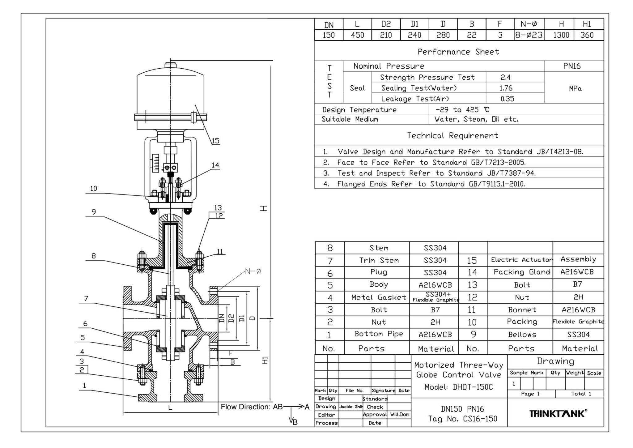
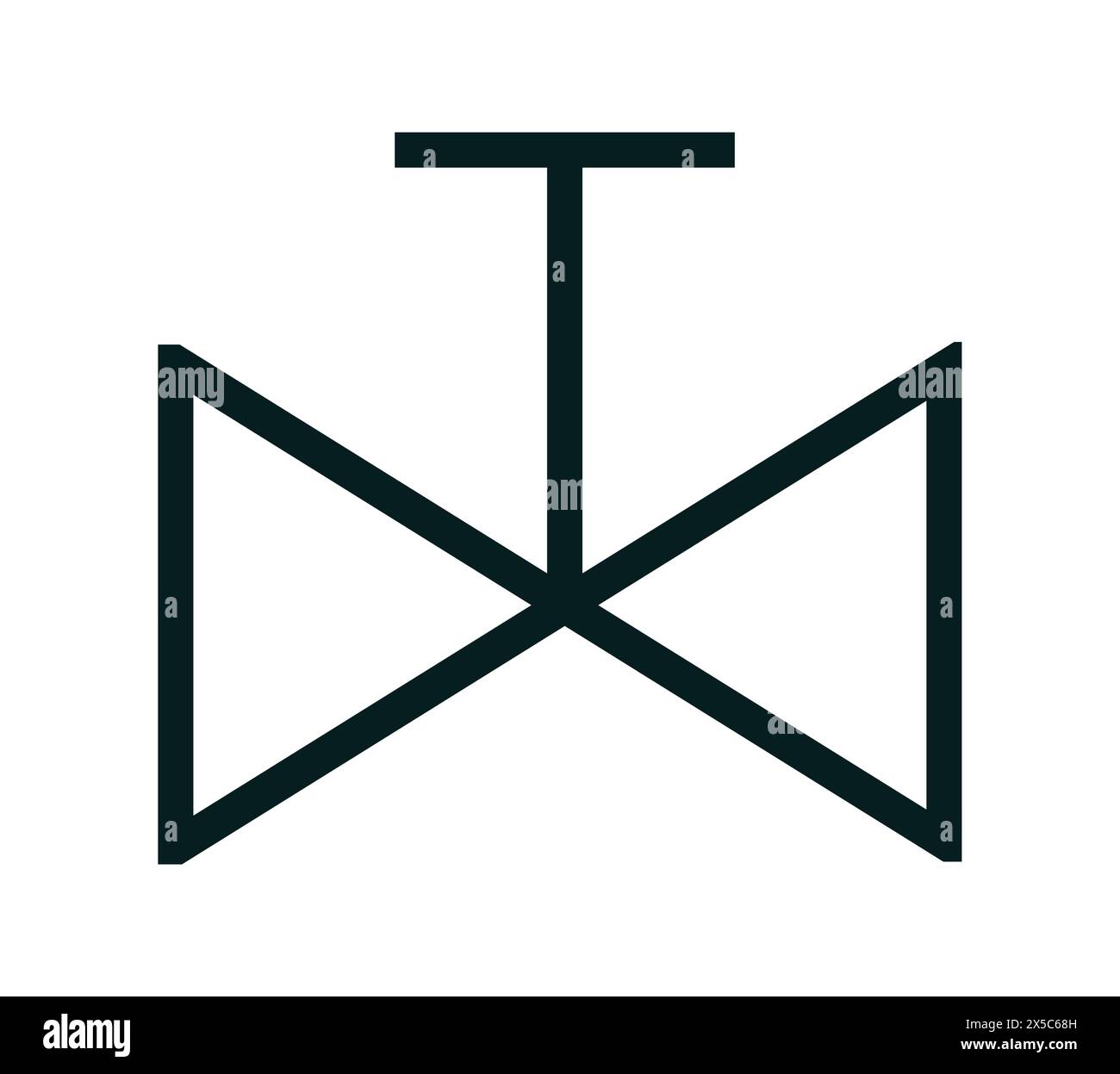
A 3-way valve symbol is a graphical representation used in engineering drawings, such as Piping and Instrumentation Diagrams (P&IDs) and fluid power schematics, to denote a valve with three distinct ports. These symbols provide critical information regarding the valve’s internal flow path (mixing or diverting), its actuation method (manual, solenoid, or pneumatic), and its default fail-safe position.
As of 2026, the standardization of these symbols remains governed primarily by the International Organization for Standardization (ISO) and the International Society of Automation (ISA). Whether you are designing a high-pressure hydraulic system or a complex chemical processing plant, accurately interpreting and applying the 3-way valve symbol is essential for operational safety, maintenance efficiency, and regulatory compliance.
The Role of Standards in Valve Symbology
In industrial engineering, a "sketch" is insufficient; documentation must adhere to rigorous standards to ensure that a technician in Germany can interpret a schematic designed in Japan or the United States. Two primary sets of standards define how a 3-way valve symbol is drawn:
- ISA-5.1 (Instrumentation Symbols and Identification): This is the gold standard for P&IDs used in the process industries (oil and gas, water treatment, chemical). The symbols here are more abstract, focusing on the function of the valve within a process flow.
- ISO 1219-1 (Fluid Power Systems and Components): This standard is used for hydraulic and pneumatic schematics. These symbols are more "functional," using boxes (envelopes) and arrows to show exactly how fluid moves through the valve in different positions.
Understanding which standard is being used is the first step in correctly identifying a 3-way valve symbol. Using an ISA symbol in a hydraulic circuit, or vice versa, can lead to significant installation errors and safety hazards.
Basic Anatomy of a 3-Way Valve Symbol
While specific details vary by standard, most 3-way valve symbols share a common visual logic.
The Port Connections
A 3-way valve, by definition, has three ports: an inlet, an outlet, and a third port that serves as either a second inlet (in mixing applications) or a second outlet (in diverting applications). In a standard P&ID, this is represented by two triangles meeting at a center point, with a third line connecting to that center point from a perpendicular angle.
The Flow Path (L-Port vs. T-Port)
One of the most critical aspects of a 3-way valve symbol is the indication of the internal ball or plug configuration. This is often represented by a small "L" or "T" shape within the valve body or adjacent to it.
- L-Port Symbols: The "L" configuration (also called a "90-degree" or "diverter" valve) connects the center port to either of the two side ports, but never all three at once. In a schematic, the symbol will often show a curved arrow or a specific line path indicating that flow can only move in an L-shaped direction.
- T-Port Symbols: The "T" configuration is more versatile. It can connect two ports, all three ports, or act as a standard flow-through valve. The symbol will include a T-shaped indicator to show that the flow can be split or combined across all three openings.
3-Way Valve Symbols in P&IDs (ISA Standards)
In P&ID documentation, the 3-way valve symbol is often simplified to focus on the control logic. The basic symbol is three triangles pointing toward a common center. However, the complexity increases when you add the actuator—the component that actually moves the valve.
Actuator Modifiers
The symbol sitting on top of the valve body tells the reader how the valve is operated:
- Manual (Hand Lever): Represented by a T-shaped handle or a simple line above the valve.
- Diaphragm (Pneumatic): Represented by a semi-circle or an "umbrella" shape. This indicates the valve is moved by air pressure.
- Solenoid (Electric): Represented by a small box containing the letter "S." This is common in automated systems where a PLC (Programmable Logic Controller) triggers the valve.
- Piston: Represented by a square box with a T-shape inside, indicating a cylinder-driven movement.
Fail-Safe Positions
In 2026, safety protocols for automated valves are more stringent than ever. P&ID symbols for 3-way valves often include arrows or letters (FO for Fail Open, FC for Fail Closed, or FL for Fail Last) to indicate what happens if power or air pressure is lost. For a 3-way valve, the "Fail" position might indicate which specific port remains open during a system failure, which is vital for preventing over-pressurization in chemical reactors.
3-Way Valve Symbols in Hydraulics and Pneumatics (ISO 1219)
Hydraulic symbols are more literal than P&ID symbols. They use "envelopes" (squares) to represent the different states of the valve. A 3-way valve is typically a "3/2 valve," meaning it has 3 ports and 2 positions.
The Two-Square System
A standard 3/2-way hydraulic valve symbol consists of two adjacent squares.
- The "Neutral" Square: This shows the flow path when the valve is at rest (often held there by a spring).
- The "Actuated" Square: This shows the flow path when the valve is energized (by a solenoid or lever).
Inside these squares, you will see arrows. An arrow pointing from Port 1 to Port 2 indicates flow. A "T" shape (not to be confused with the T-port mentioned earlier) inside these squares indicates a "blocked" port, where the fluid cannot pass.
Identification Numbers
In ISO standards, ports are often numbered:
- Port 1: Pressure (Inlet).
- Port 2: Working Line (Outlet).
- Port 3: Exhaust or Tank (Return line).
Seeing these numbers next to the 3-way valve symbol allows the technician to ensure the hoses are connected to the correct ports during assembly.
Comparison of 3-Way Valve Types and Symbols
The following table outlines the most common configurations encountered in 2026 industrial environments, distinguishing between their physical function and how they are represented on paper.
| Valve Type | Primary Function | Common Symbol Feature | Best Use Case |
|---|---|---|---|
| Diverting (L-Port) | Directs flow from one source to one of two destinations. | L-shaped flow path indicator. | Switching between two storage tanks. |
| Mixing (T-Port) | Combines flow from two sources into one outlet. | T-shaped flow path indicator. | Controlling water temperature by mixing hot/cold. |
| Solenoid 3/2 | High-speed automated switching. | Box with "S" or "M" (for Magnet). | Pneumatic cylinder control. |
| Bypass Valve | Redirects flow around a piece of equipment. | Three triangles with bypass line logic. | Heat exchanger maintenance without shutdown. |
| Pressure Relief | Venting excess pressure to a safe outlet. | Spring symbol on one side of the valve. | Safety systems in steam lines. |
Practical Interpretation: Reading the Logic
When encountering a 3-way valve symbol on a blueprint, you should follow a systematic approach to ensure you understand its operation:
- Identify the Source: Look for the line labeled "P" (Pressure) or the line coming from the pump. This is your primary inlet.
- Determine the Default State: In a multi-envelope symbol (ISO), the square that the lines are currently connected to in the drawing is the "de-energized" or "rest" position.
- Trace the Actuation: Look at the symbol on the side of the valve (a spring, a solenoid, or a pedal). If the solenoid is energized, mentally "slide" the other square into place to see how the flow changes.
- Verify the Porting: In a P&ID, check for the "L" or "T" designation. If a valve is intended to mix two chemicals, an L-port valve would be a catastrophic design error, as it can only select one at a time.
Common Mistakes in Symbol Interpretation
Even experienced engineers can misinterpret 3-way valve symbols if they are not paying close attention to the specific standards used by the drafter.
- Confusing 3-Way with 2-Way: A 3-way valve has three ports, but in some drawings, the third port (exhaust) might be vented to the atmosphere and shown as a small triangle or an inverted "T" rather than a full line. This can lead to the mistaken belief that the valve is a simple on/off (2-way) valve.
- Ignoring the Spring Return: If a 3-way valve symbol includes a zigzag line on one side, it is a spring-return valve. This means it will only stay in the second position as long as the actuator (like a solenoid) is powered. Once power is lost, it will snap back to the default position.
- Misjudging Center Positions: In 3-way, 3-position valves (rare but used in specific hydraulic circuits), there is a middle square. Interpreting the "all ports blocked" vs. "all ports open" center position is critical for preventing mechanical drift in heavy machinery.
Professional Advice Limitation
This guide is for educational and informational purposes regarding engineering symbology. Drawing interpretations should always be verified against the specific project's "Legend and Symbols" sheet. Errors in interpreting valve symbols in high-pressure or hazardous chemical environments can lead to equipment failure, injury, or death. Always consult with a licensed Professional Engineer (PE) or a certified fluid power specialist before modifying or installing industrial valve systems.
Frequently Asked Questions
1. What is the difference between an L-port and a T-port 3-way valve symbol?
The L-port symbol indicates that the valve can connect the center port to either the left or right port, typically at a 90-degree turn, but cannot connect all three. The T-port symbol indicates that the valve can connect all three ports simultaneously or various combinations thereof. In schematics, these are often marked with a small "L" or "T" inside a circle near the valve body.
2. How do I identify a solenoid-actuated 3-way valve?
In a P&ID, look for a small square box on top of the valve triangles containing the letter "S." In an ISO hydraulic schematic, look for a rectangle on the end of the valve envelope with a diagonal line through it, which represents the solenoid coil.
3. Does the direction of the triangles in the symbol matter?
Yes. The triangles generally point toward the flow path or the center of the valve body. In more detailed P&IDs, the orientation can indicate whether the valve is currently "normally open" or "normally closed" relative to a specific process line.
4. What does a 3-way valve symbol with a "mushroom" head mean?
A mushroom-shaped symbol on the actuator line indicates a manual "push-button" valve, frequently used for emergency stops or manual overrides in pneumatic control panels.
5. Why are some 3-way valve symbols drawn with two squares and others with only one?
Symbols with two (or more) squares are ISO fluid power symbols. Each square represents a physical "state" or "position" of the valve. P&ID symbols (ISA) typically use a single representation of the valve body and use text or actuator symbols to describe its multi-position functionality, as P&IDs focus more on the process than the mechanical switching of the valve.
Next Steps for Technical Accuracy
To ensure the highest level of accuracy in your documentation, always cross-reference your "3 way valve symbol" with the Master Legend Sheet provided at the beginning of the drawing set. As of 2026, many companies use customized versions of ISA-5.1 to account for digital positioners and smart-valve feedback loops. If you are using CAD software, ensure your symbol libraries are updated to the latest ISO 1219:2026 or ISA-5.1 standards to avoid discrepancies between design and physical implementation.