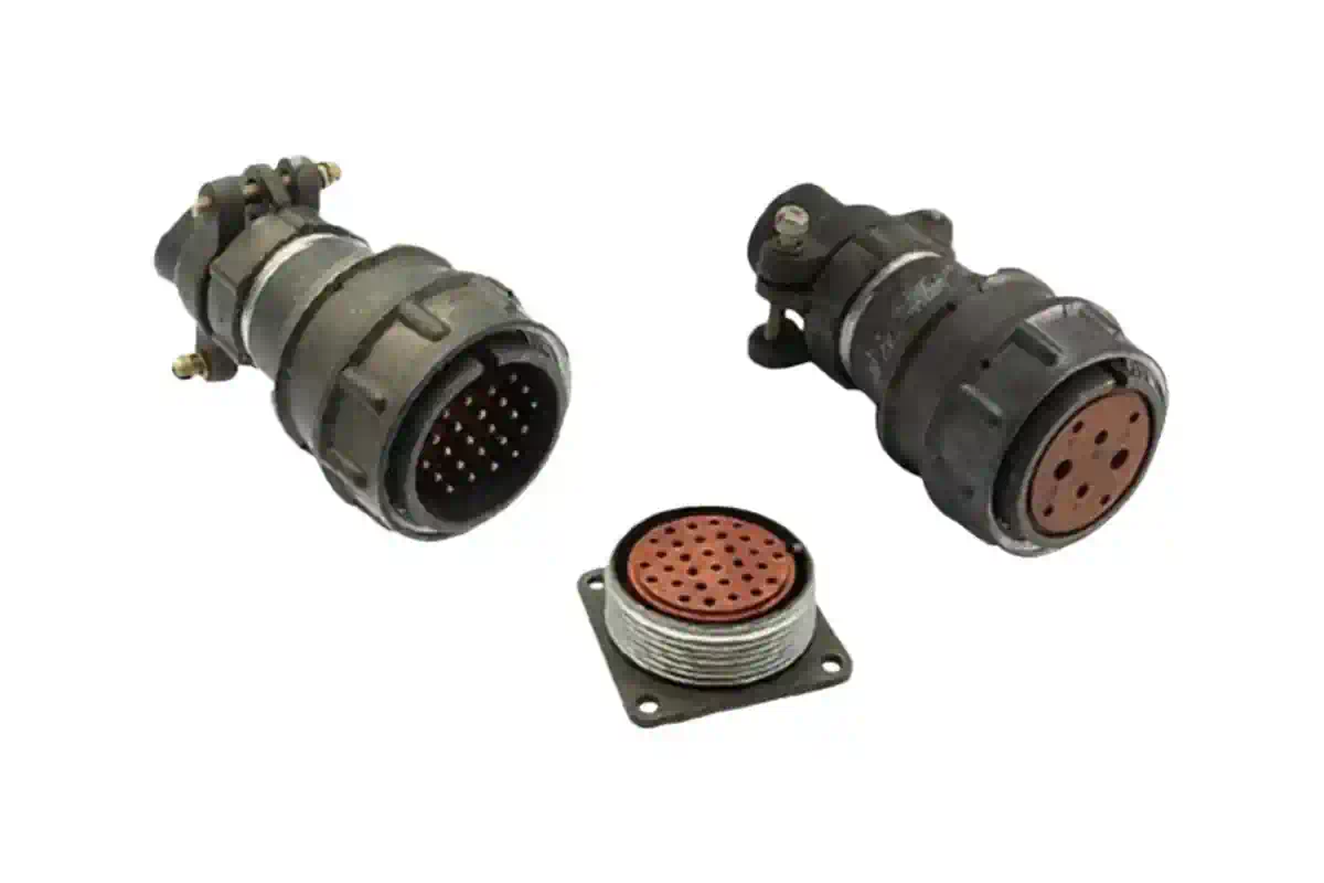
MIL-DTL-5015 connectors are rugged, circular interconnects designed for heavy-duty military and industrial environments. They utilize threaded coupling and diverse insert arrangements to facilitate reliable power and signal distribution. These connectors are prized for their high current capacity, durability under vibration, and standardized intermateability across various global manufacturers.
The Evolution and Standardization of the 5015 Series
The 5015 series, originally designated as MIL-C-5015, represents one of the most successful and enduring connector standards in history. Developed during World War II for aeronautical applications—earning them the common name "AN" (Army-Navy) connectors—they were designed to provide a standardized, interchangeable interface for electrical systems in tanks, aircraft, and ships. Over the decades, the specification transitioned to MIL-DTL-5015, reflecting its status as a "Detail Specification" maintained by the United States Department of Defense.
As of 2026, while many modern aerospace designs have migrated toward high-density miniature connectors like the MIL-DTL-38999 series, the 5015 remains a primary choice for heavy industrial machinery, rail transportation, and legacy military hardware. Its longevity is attributed to its simplicity and physical robustness. The standard defines the mechanical dimensions, materials, and performance requirements, ensuring that a plug from one manufacturer will reliably mate with a receptacle from another, provided they share the same shell size and insert arrangement.
The specification is currently divided into several series. The most common are Series I (solder contacts) and Series II/III (crimp contacts). In industrial contexts, these are often referred to as "Comm-5015" or industrial equivalents, which may deviate slightly from military plating requirements while maintaining the core mechanical envelope.
Mechanical Design and Construction
The 5015 connector is characterized by its circular aluminum alloy shell and threaded coupling mechanism. This design offers a significant mechanical advantage, as the threads provide high torque resistance and prevent accidental decoupling in environments prone to intense vibration or shock.
Shell Components and Materials
The shell is the outer protective housing of the connector. In the 2026 manufacturing landscape, the standard material remains high-grade aluminum alloy, though stainless steel variants are available for highly corrosive environments (such as maritime or chemical processing). The shells are typically plated to prevent oxidation. Historically, olive drab cadmium over nickel was the military standard due to its excellent corrosion resistance and lubricity. However, due to environmental regulations, modern 5015 connectors are frequently specified with Zinc-Nickel (Black or Grey) or Electroless Nickel finishes to remain RoHS and REACH compliant while providing similar protection.
Inserts and Dielectrics
Inside the shell lies the insert, which holds the contacts in a specific orientation. These inserts are made from resilient materials, most commonly neoprene or silicone rubber in environmental classes, or rigid thermoset plastics in non-environmental versions. The choice of insert material dictates the connector's operating temperature range and resistance to fluids like hydraulic oil, jet fuel, and cleaning solvents.
Coupling Mechanism
The threaded coupling is the defining feature of the 5015. Unlike "bayonet" style connectors (which lock with a quarter-turn), the 5015 requires multiple rotations to fully seat. This provides a very secure connection that is less likely to "walk" open under low-frequency, high-amplitude vibration. Many 5015 plugs also include a "coupling nut" with knurled surfaces or hex flats to facilitate hand-tightening or the use of a torque wrench.
Understanding Service Classes and Environmental Ratings
The MIL-DTL-5015 specification defines several "Classes" that determine how the connector handles environmental stressors such as moisture, altitude, and temperature. Selecting the correct class is critical for the longevity of the interconnect system.
- Class A (Solid Shell): These are general-purpose connectors intended for use where no environmental seal is required. They are common in indoor industrial settings or within protected enclosures.
- Class B (Split Shell): These feature a shell that can be disassembled for easy access to the solder joints. They are rarely used in new designs but are common in legacy maintenance.
- Class E/F (Environmental): These are the workhorses of the series. Class E includes a grommet seal at the wire entry point to prevent moisture ingress. Class F adds a strain relief clamp to protect the wires from mechanical tension.
- Class R (Lightweight Environmental): A shorter, lighter version of the Class F, designed for applications where weight and space are at a premium, such as in 2026-era UAV or robotics platforms.
Ingress Protection (IP) Ratings
While MIL-DTL-5015 is a military standard, it is often mapped to IP ratings for industrial customers. When properly mated with appropriate backshells and cable glands, environmental 5015 connectors typically achieve IP67 or even IP68 ratings, meaning they are dust-tight and protected against temporary immersion in water.
Technical Specifications: Voltage, Current, and Contacts
One of the primary reasons engineers specify 5015 connectors is their ability to carry high current alongside signal lines in a single interface. The physical size of the contacts determines the current-carrying capacity.
Contact Sizes and Current Ratings
The 5015 standard utilizes contact sizes ranging from 16 (the smallest) to 0 (the largest). As of 2026, the rated current capacity for these contacts is generally accepted as follows:
- Size 16: 13 Amps
- Size 12: 23 Amps
- Size 8: 46 Amps
- Size 4: 80 Amps
- Size 0: 150 Amps
Service Voltage Ratings
The spacing between contacts (creepage and clearance) determines the service rating. The 5015 specification defines several levels, which are essential for safety and preventing electrical arcing.
| Service Rating | Operating Voltage (DC) | Operating Voltage (AC RMS) | Test Voltage (AC RMS) |
|---|---|---|---|
| Inst. | 250V | 200V | 1000V |
| A | 700V | 500V | 2000V |
| D | 1250V | 900V | 2800V |
| E | 1750V | 1250V | 3500V |
| B | 2450V | 1750V | 4500V |
| C | 4200V | 3000V | 7000V |
Note: These ratings are for sea-level operation. Voltage de-rating is required for high-altitude applications.
Termination Methods: Solder vs. Crimp
When specifying a 5015 connector, the user must choose between solder and crimp terminations. This choice impacts assembly time, field repairability, and mechanical reliability.
Solder Contacts (The "MS310" Tradition)
Solder contacts are permanently bonded to the insert. The technician strips the wire, inserts it into a "solder cup," and applies heat and solder.
- Pros: Lower initial cost for the connector; no specialized crimp tools required; excellent for small-batch production.
- Cons: Higher risk of "cold solder joints"; requires high operator skill; heat can damage the insert if applied too long; difficult to repair in the field.
Crimp Contacts (The "MS345" Modern Standard)
Crimp contacts are attached to the wire using a mechanical tool and then inserted into the connector shell.
- Pros: Highly repeatable and consistent mechanical bond; no heat required; contacts can be removed and replaced using extraction tools (Rear-Release); better performance in high-vibration environments.
- Cons: Requires expensive, calibrated crimp tools (e.g., M22520 series); slightly higher component cost.
Shell Styles and Mounting Options
The 5015 series offers a variety of shell geometries to accommodate different mounting requirements. Understanding these "MS" (Military Standard) prefixes is essential for correct part identification.
- MS3100 (Wall Mount Receptacle): Designed to be bolted to a panel or bulkhead. It features a backshell for cable attachment.
- MS3101 (In-Line Receptacle): Used for "cable-to-cable" connections. It looks like a plug but has the mating threads on the outside.
- MS3102 (Box Mount Receptacle): A low-profile version of the MS3100 that does not accept a backshell. It is intended for mounting directly onto a junction box where the wires terminate immediately inside.
- MS3106 (Straight Plug): The standard "male" end of the connection that attaches to the cable.
- MS3108 (Right Angle Plug): Used in tight spaces where the cable must exit at a 90-degree angle to the connection point.
Critical Selection Criteria for 2026 Applications
Choosing the right 5015 connector requires a systematic approach to ensure both electrical performance and environmental compliance.
1. Circuit Requirement Analysis
Determine the total number of conductors and the maximum current each will carry. This will dictate the Insert Arrangement. For example, arrangement 18-1 contains 10 size-16 contacts, while 24-10 contains 7 size-8 contacts. Using a single large contact for power and multiple small contacts for signal is a common 5015 configuration.
2. Environmental Exposure
Assess whether the connector will face rain, jet fuel, or salt spray. If moisture is a factor, avoid Class A and specify Class E, F, or R. For 2026 industrial automation, Class F with an integrated strain relief is the most robust choice for moving robotic arms or vibrating machinery.
3. Mating Frequency
Threaded connectors like the 5015 are not designed for thousands of mating cycles. They are intended for "set and forget" applications or systems that are disconnected only for maintenance. If your application requires daily plugging/unplugging, consider a bayonet-style equivalent (like the VG95234) which uses the same 5015 insert patterns but a faster locking mechanism.
4. Regulatory Compliance
As of 2026, many government and commercial contracts explicitly forbid cadmium plating. Ensure the part number suffix reflects an alternative finish like A232 (Black Zinc Cobalt) or A240 (Zinc Nickel) to avoid project delays or legal non-compliance.
Common Mistakes and Troubleshooting
Despite their ruggedness, 5015 connectors can fail if mismanaged. One common issue is over-tightening. While a secure fit is necessary, excessive torque can strip the threads or deform the shell. Using a dedicated connector wrench is highly recommended over standard pliers.
Another frequent failure point is the grommet seal. If the wire diameter is too small for the hole in the sealing grommet, moisture will "wick" down the wire and into the contact area, causing short circuits. When using thin-walled wires in 2026, technicians must use "wire sealing boots" or shrink tubing to build up the diameter to ensure a proper environmental seal.
Finally, cross-mating remains a risk. Because the 5015 is a standard, it is possible to find connectors with the same shell size but different insert rotations (Keying). The standard "N" (Normal) keying is most common, but versions with W, X, Y, or Z rotations exist to prevent a user from plugging the "Power" cable into the "Data" receptacle. Always verify the keying position during the design phase.
Frequently Asked Questions
Can I mate an Amphenol 5015 with an ITT Cannon 5015?
Yes. One of the primary advantages of the MIL-DTL-5015 standard is intermateability. As long as both manufacturers adhere to the MS (Military Standard) specifications for shell size, insert arrangement, and contact gender, they will mate and function correctly. However, always ensure that the environmental classes are compatible to maintain the integrity of the seal.
What is the difference between MIL-DTL-5015 and MIL-DTL-26482?
While both are circular connectors, the 5015 uses a threaded coupling and is generally larger, designed for higher power applications. The 26482 series typically uses a bayonet (three-pin) quick-disconnect coupling and is higher density, meaning it fits more contacts into a smaller shell. The 26482 is preferred for signal-heavy applications, while the 5015 is the standard for power distribution.
How do I identify a 5015 part number?
A typical military part number looks like MS3106F18-1S.
- MS3106 is the shell style (Straight Plug).
- F is the environmental class (Environmental with strain relief).
- 18 is the shell size.
- 1 is the insert arrangement.
- S is the contact gender (Socket). Most manufacturers also have their own proprietary numbering systems that map directly to these MS codes.
Are 5015 connectors suitable for high-speed data?
Generally, no. The 5015 series was designed before the era of high-speed Ethernet and fiber optics. While they can carry low-speed serial data (RS-232, RS-485), they lack the shielding and twisted-pair integrity required for modern Cat6 or high-frequency signals. In 2026, if you need high-speed data in a 5015-style shell, you should look for "Quadrax" contact inserts specifically designed for data integrity.
Why is cadmium plating being replaced in 5015 connectors?
Cadmium is a toxic heavy metal and a known carcinogen. Environmental regulations globally (like REACH and RoHS) have restricted its use. In 2026, manufacturers have perfected alternative platings like Black Zinc Nickel (ZnNi), which offers superior corrosion resistance (500+ hours of salt spray) and is electrically conductive, making it an ideal, safer replacement for traditional olive drab cadmium.
Final Recommendation
For those designing systems in 2026, the MIL-DTL-5015 Class F with Zinc Nickel plating and crimp contacts remains the gold standard for high-reliability industrial power and signal applications. It balances environmental protection, mechanical durability, and ease of maintenance. When procuring these components, always verify the insert arrangement against the current requirements of your hardware and ensure that all accessories, such as backshells and dust caps, are selected from the same environmental class to prevent premature system failure.