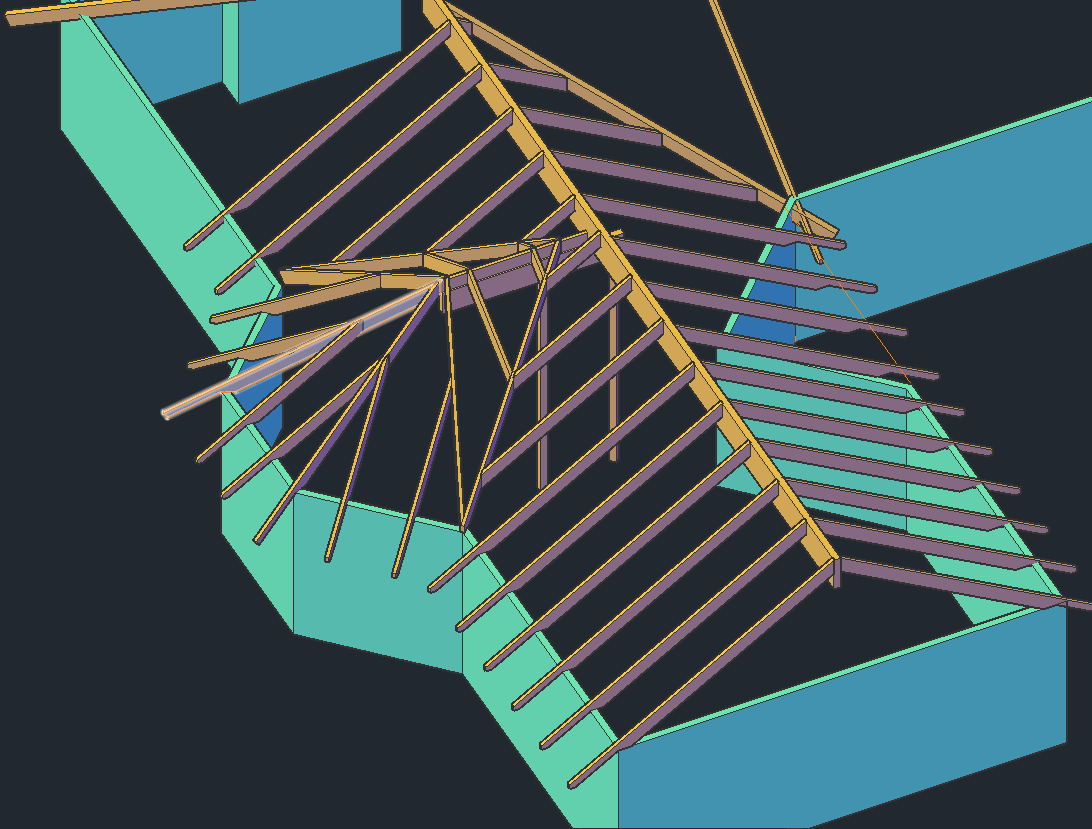
A 3D roof drawing provides a mathematically precise, three-dimensional representation of a building's roofing structure, integrating pitch, span, azimuth, and material specifications into a unified digital model. These drawings are essential for accurate material estimation, structural analysis, and compliance with modern architectural engineering standards.
Introduction to 3D Roof Modeling
In the evolution of architectural drafting and construction planning, traditional two-dimensional blueprints have increasingly given way to advanced three-dimensional visualization tools. A 3D roof drawing represents more than just a realistic image of a building’s upper structure; it is a complex data model containing geometric, topological, and material attributes. For general contractors, structural engineers, and roofing professionals, transitioning from flat line drawings to spatial models eliminates ambiguities inherent in multi-view 2D projections.
Modern roofing projects demand extreme precision. A minor miscalculation in roof pitch or valley length can lead to costly material waste, structural failure, or compliance issues with local building codes. 3D roof drawings bridge the gap between architectural design and field execution. By simulating the physical geometry of ridges, hips, valleys, rakes, and eaves in a virtual environment, stakeholders can analyze water runoff patterns, evaluate solar panel placement viability, and generate automated material cut lists with high fidelity.
Core Geometric Principles and Terminology
Understanding a 3D roof drawing requires familiarity with the fundamental geometric terminology that defines roof construction. Unlike simple 3D models used in video games or conceptual art, technical roof drawings rely on strict geometric constraints, coordinate systems, and vector calculations.
Every roof model is built upon a coordinate system where vertices, edges, and faces correspond to real-world dimensions. The key structural components represented in a technical 3D roof drawing include:
- Pitch and Slope: The steepness of the roof, typically expressed as a ratio of vertical rise to horizontal run (e.g., 4:12) or as an angle in degrees. In 3D software, the pitch dictates the slope angle of intersecting planes.
- Ridge: The highest horizontal line formed by the meeting of two upward-sloping roof planes.
- Hip: The external angle formed by the intersection of two adjacent sloping roof sides running from the ridge to the eaves.
- Valley: The internal angle formed by the intersection of two inclined roof planes, creating a channel where water runoff collects and directs downward.
- Eave and Rake: The eave represents the lower horizontal edge of the roof that overhangs the exterior wall, while the rake is the inclined edge of a gable roof running from the eave to the ridge.
These elements are mathematically linked. When an operator modifies the span or pitch of one section in a 3D modeling application, the software's parametric engine automatically adjusts adjacent planes to maintain structural closure and geometric integrity.
Data Sources and Capture Technologies
Creating a highly accurate 3D roof drawing requires precise spatial data. Historically, this data was gathered through manual field measurements using tape measures, laser distance meters, and magnetic pitch finders—a time-consuming process fraught with human error and safety risks associated with walking on pitched surfaces. Today, advanced data capture technologies feed directly into 3D modeling pipelines.
Aerial Photogrammetry
Aerial photogrammetry involves capturing overlapping high-resolution photographs of a property from unmanned aerial vehicles (drones) or manned aircraft. Specialized software processes these images using Structure-from-Motion (SfM) algorithms to triangulate common points across multiple frames, generating dense point clouds and textured 3D meshes. This method provides rapid data acquisition for large or complex commercial structures without requiring physical roof access.
LiDAR (Light Detection and Ranging)
LiDAR technology uses ultraviolet, visible, or near-infrared light to map objects. Airborne or terrestrial LiDAR systems emit rapid pulses of light toward the roof surface, measuring the time it takes for each pulse to return. This creates millions of precise 3D data points—known as a LiDAR point cloud—representing the exact topography of the roof, including subtle deformations, protrusions, and HVAC units.
Terrestrial Laser Scanning and Manual Inputs
For buildings requiring millimeter-level precision or historical preservation, terrestrial laser scanners positioned on the ground capture comprehensive point clouds. Alternatively, estimators can input traditional manual field measurements into parametric software templates. While slower, manual input remains common for smaller residential retrofits where automated aerial capture is cost-prohibitive or obstructed by dense tree cover.
Software Ecosystem and Modeling Workflows
The software tools used to generate 3D roof drawings range from specialized, automated estimation platforms to comprehensive Building Information Modeling (BIM) suites. Selecting the appropriate software depends on the project scope, required output formats, and the user's technical expertise.
| Software Category | Primary Function | Typical Use Case | Common Industry Standards |
|---|---|---|---|
| BIM Suites | Full lifecycle building design and data management | Architectural design, structural engineering, clash detection | Autodesk Revit, Archicad |
| Dedicated Roofing Tools | Automated takeoff and precise material estimation | Residential and commercial roofing bids, contractor proposals | EagleView, RoofSnap, Skycatch |
| General 3D CAD | Flexible surface and solid modeling | Custom geometric designs, artistic or complex freeform roofs | AutoCAD, Rhino 3D, SketchUp |
The workflow for generating a professional 3D roof drawing typically follows a standardized sequence:
- Data Ingestion: Importing aerial imagery, point clouds, or blueprints into the modeling software and establishing the project scale using a known reference dimension.
- Outline Trace: Tracing the perimeter of the exterior walls or roof overhang to establish the foundational footprint.
- Plane Generation: Defining individual roof planes by assigning pitch, direction, and elevation parameters to each section of the footprint.
- Intersection and Cleanup: Allowing the software to calculate automatic intersections (ridges, hips, valleys) and manually refining complex junctions, dormers, or architectural penetrations.
- Attribute Assignment: Applying material specifications—such as asphalt shingle types, standing seam metal profiles, underlayment grades, and flashing details—to calculate surface areas and linear footages accurately.
Applications in Construction, Estimation, and Engineering
A technical 3D roof drawing serves multiple downstream disciplines throughout a building's lifecycle. By establishing a single source of truth for spatial data, these models streamline communication between architects, contractors, insurance adjusters, and property owners.
Accurate Material Estimation and Takeoffs
Manual calculations of roof areas often result in material waste due to over-ordering or project delays due to under-ordering. 3D roof drawings account for complex geometry, pitch multipliers, and waste factors (such as hip and valley cut-offs). Automated takeoffs generate precise counts for bundles of shingles, linear feet of ridge caps, square footage of underlayment, and counts of ventilation penetrations.
Structural Analysis and Load Calculations
Engineers use 3D roof models to simulate environmental loads. By exporting the geometry into structural analysis software, professionals can evaluate dead loads (the weight of the roofing materials themselves) and live loads (such as snow accumulation and wind uplift forces). Accurate pitch and orientation data are also critical for calculating solar irradiance, determining whether a roof can support photovoltaic arrays without structural reinforcement.
Claims Processing and Insurance Verification
In the insurance sector, 3D roof drawings created from pre- and post-storm aerial imagery provide indisputable evidence for hail and wind damage claims. Adjusters can measure exact damaged surface areas, identify missing shingles, and verify roof geometry remotely, accelerating claims settlement while minimizing fraudulent or inflated repair estimates.
Common Modeling Challenges and Troubleshooting
Despite advancements in automation and computing power, generating flawless 3D roof drawings presents several technical hurdles that require expert intervention.
- Obstructed Aerial Views: Overhanging trees, heavy shadows, or architectural overhangs can obscure ground or roof features in aerial imagery, leading to gaps in photogrammetry point clouds. Solution: Supplement aerial data with manual terrestrial measurements or drone flights timed during optimal lighting conditions.
- Complex Multi-Level Intersections: Buildings with multiple additions, varying eave heights, and irregular intersecting gables often confuse automated roof detection algorithms, creating overlapping or unclosed geometry. Solution: Break the roof down into simpler sub-assemblies or primary massing blocks, model them individually, and join them manually within the CAD environment.
- Sagging or Aged Roofs: Existing structures that have suffered structural degradation or sagging over time will not conform to ideal geometric planes. If a 3D model assumes perfect flatness, material calculations will be inaccurate. Solution: Use high-density LiDAR point clouds that capture actual surface deviations rather than idealized parametric shapes.
Future Trends in 3D Roof Documentation
The technical landscape of 3D roof drawing continues to evolve alongside advances in artificial intelligence and spatial computing. Machine learning algorithms are increasingly capable of automatically detecting roof boundaries, pitches, and structural features from raw aerial imagery with minimal human intervention, reducing drawing generation time from hours to seconds. Furthermore, integration with augmented reality (AR) allows field contractors to project 3D roof models directly onto physical job sites through mobile devices or smart helmets, verifying installation accuracy in real time and bridging the gap between digital design and physical construction.
Frequently Asked Questions
What is the difference between a 2D roof plan and a 3D roof drawing?
A 2D roof plan is a flat, top-down orthogonal projection showing layout dimensions without elevation depth, making pitch and height relationships difficult to interpret visually. A 3D roof drawing incorporates spatial coordinates, pitch angles, and depth, allowing for precise volume calculations, realistic visualization, and automated material takeoffs.
How accurate are automated 3D roof models generated from drone imagery?
Modern photogrammetry and LiDAR models generated from high-resolution drone imagery typically achieve horizontal and vertical accuracies within one to two inches, provided ground control points and proper camera calibration are utilized. This level of precision is generally sufficient for commercial estimation and engineering design.
Can 3D roof drawings help in designing solar panel installations?
Yes. 3D roof drawings provide exact measurements of surface orientation (azimuth), pitch angle, and unshaded surface area. Solar design software uses these models to calculate precise solar irradiance levels, optimize panel placement, and determine structural load limits for mounting hardware.
What file formats are commonly used to export 3D roof drawings?
Depending on the downstream application, 3D roof models are commonly exported as DXF or DWG files for CAD software, IFC (Industry Foundation Classes) for BIM workflows, OBJ or FBX for 3D visualization, or PDF reports containing tabular material takeoffs and dimensional diagrams for contractors.
Do I need specialized engineering training to create a basic 3D roof drawing?
Basic 3D roof drawings for residential estimation can be created using intuitive, cloud-based software platforms that require minimal technical training. However, complex commercial structures, structural load calculations, and formal architectural engineering deliverables require professional expertise in advanced CAD or BIM environments.
Practical Next Actions
To successfully implement 3D roof drawing workflows for an upcoming project, begin by defining the required level of detail based on your primary objective—whether it is a preliminary material estimate, an insurance claim verification, or a full structural renovation. Select an appropriate software platform that matches your team's technical capabilities, and establish a reliable data capture pipeline using certified aerial imagery providers or direct on-site laser scanning. Always verify critical structural dimensions against physical site measurements before finalizing material orders or engineering submittals.