The Arduino Uno CNC Shield is an expansion board that allows you to transform a standard Arduino Uno into a powerful, low-cost controller for CNC machines, 3D printers, and laser cutters. By interfacing with modular stepper motor drivers, it manages the complex timing and power requirements needed to translate digital G-code instructions into precise physical movement.
For hobbyists, engineers, and makers in 2026, the CNC Shield remains the gold standard for entry-level motion control. While 32-bit controllers have gained traction for high-end industrial applications, the simplicity, affordability, and massive community support of the Arduino Uno/CNC Shield ecosystem make it the primary choice for DIY builds. This guide provides a comprehensive breakdown of how the shield operates, its technical architecture, and how to successfully implement it in your next project.
Understanding the Arduino Uno CNC Shield
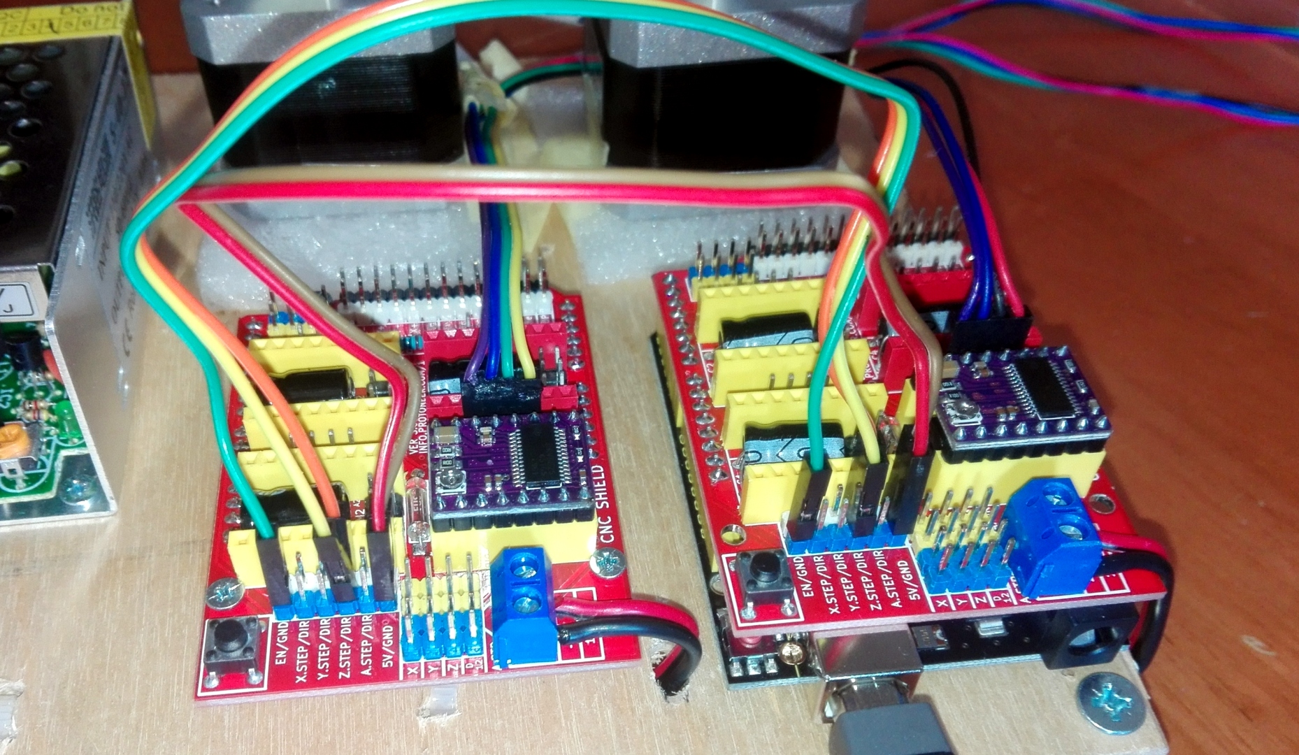
The Arduino Uno CNC Shield, most commonly found in version 3.00 or 3.10, is a "shield" in the literal sense: it sits directly on top of the Arduino Uno, plugging into its headers. Its primary purpose is to simplify the wiring and hardware management of a multi-axis motion system.
Without this shield, a user would need to manually wire dozens of connections between the Arduino, various motor drivers, limit switches, and power supplies. The shield consolidates these connections into a single PCB (Printed Circuit Board) with dedicated sockets for stepper drivers, screw terminals for power, and pin headers for peripherals. This modular design means that if a single motor driver fails, you can replace a $5 component rather than an entire $100 control board.
The Role of the Arduino Uno
The Arduino Uno serves as the "brain" of the operation. It runs a specialized firmware—most often GRBL—which interprets G-code commands (standardized numerical control instructions) received from a computer via USB. The Uno processes these commands and sends high-speed digital signals (Step and Direction) to the CNC Shield.
The Role of the CNC Shield
The CNC Shield acts as the "nervous system." It distributes the low-voltage logic signals from the Arduino to the high-voltage motor drivers. It also handles the power distribution, ensuring that the motors receive the necessary current (typically 12V to 36V) without damaging the Arduino’s sensitive 5V logic circuits.
Core Components and Hardware Architecture
To fully understand the CNC Shield, one must break down the board into its functional zones. Each zone is designed to handle a specific aspect of the CNC machine's operation.
1. Stepper Motor Driver Sockets
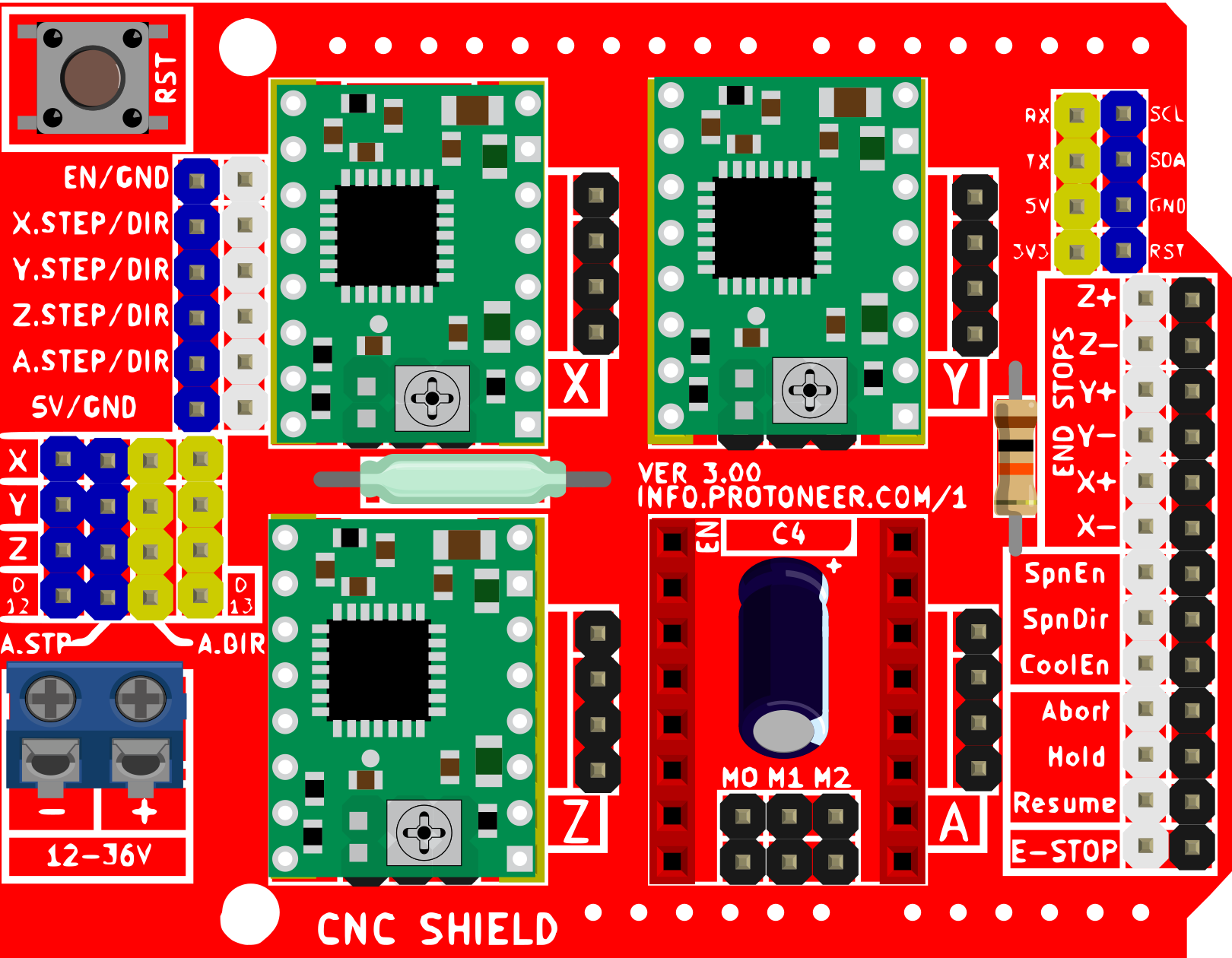
The board features four distinct sockets labeled X, Y, Z, and A. These are designed to hold "pololu-style" stepper drivers, such as the A4988 or the DRV8825.
- X, Y, and Z Axes: These are the primary movement axes for most machines.
- A Axis: This is a versatile fourth slot. Using jumpers on the board, it can be configured to "clone" the X, Y, or Z axis (useful for machines with two motors on one axis, like a dual-drive Y-axis gantry) or be driven independently using additional digital pins from the Arduino.
2. Power Terminals
The CNC Shield features a dedicated screw terminal for an external power supply. While the Arduino is powered by 5V (via USB or DC jack), the stepper motors require much higher voltage to overcome back EMF (electromotive force) at high speeds. The shield typically supports a DC input of 12V to 36V. It is critical to ensure that your power supply voltage does not exceed the maximum rating of your chosen stepper drivers.
3. Microstepping Jumpers
Underneath each driver socket, there are sets of pins for jumpers labeled M0, M1, and M2 (or MS1, MS2, MS3). These jumpers allow you to set the "microstepping" resolution. Instead of moving in full steps (usually 200 steps per revolution), drivers can divide each step into 1/2, 1/4, 1/8, 1/16, or even 1/32 segments. This results in smoother motion and higher precision, though it reduces torque at high speeds.
4. Limit Switch and Peripheral Headers
Along the edges of the board, you will find headers for:
- Endstops/Limit Switches: Two pins for each axis (X+/X-, Y+/Y-, Z+/Z-) to prevent the machine from crashing into its physical boundaries.
- Spindle Control: Pins for Spindle Enable, Spindle Direction, and PWM (Pulse Width Modulation) for controlling spindle speed.
- Coolant Control: A dedicated pin to trigger mist or flood coolant systems.
- Control Buttons: Pins for "Abort," "Hold," and "Resume" buttons, allowing for physical interaction with the machine without using the computer interface.
Technical Specifications and Compatibility
When planning a build in 2026, it is vital to verify that your components align with the shield’s electrical limitations.
| Feature | Specification (Standard v3.0) | Notes |
|---|---|---|
| Input Voltage | 12V - 36V DC | Depends on stepper driver capacity. |
| Compatible Arduino | Arduino Uno R3 / R4 | R3 is the standard; R4 is compatible but check GRBL builds. |
| Firmware Support | GRBL 0.8, 0.9, 1.1 | v1.1 is the most stable and recommended. |
| Driver Compatibility | A4988, DRV8825, TMC2208/2209 | "Step/Dir" protocol drivers only. |
| Axis Support | 4 Axes (X, Y, Z, +1 Clone/Indep.) | Expandable via A-axis jumpers. |
| Microstepping | Up to 1/32 | Driver dependent (DRV8825 supports 1/32). |
Stepper Driver Selection: A4988 vs. DRV8825
The CNC Shield is only as capable as the drivers you plug into it. As of 2026, the two most common choices for hobbyists remain the A4988 and the DRV8825.
The A4988 (The Classic)
The A4988 is the most affordable driver. It supports up to 1/16 microstepping and can handle roughly 1.0A to 1.2A of current without active cooling. It is ideal for small laser engravers or light-duty 3D printers using NEMA 17 motors.
The DRV8825 (The Upgrade)
The DRV8825 is a more robust alternative. It supports up to 1/32 microstepping, which provides noticeably quieter and smoother operation. It can also handle higher voltages (up to 45V, though the shield limits this to 36V) and higher current (up to 2.2A with a heatsink and fan). For small CNC routers cutting wood or plastic, the DRV8825 is generally preferred.
Silent Step Sticks (TMC Series)
In recent years, the use of Trinamic (TMC) drivers like the TMC2209 on CNC shields has increased. These drivers use advanced "StealthChop" technology to make stepper motors almost silent. However, they require careful configuration of their "Standalone Mode" to work with the standard CNC shield pinout.
Software Ecosystem: The Power of GRBL
The Arduino Uno CNC Shield is designed specifically to run GRBL (pronounced "gerbil"). GRBL is an open-source, high-performance G-code parser and motion control firmware written in optimized C.
Why GRBL?
GRBL eliminates the need for expensive industrial controllers or the old-fashioned parallel port "breakout boards." It maintains incredible timing accuracy even at high step rates. Because it is open-source, it has been ported and refined over a decade, making it extremely stable for 3-axis motion.
Communicating with the Shield
To send G-code to your Arduino/CNC Shield setup, you need a "G-code Sender" on your computer. Popular options in 2026 include:
- Universal Gcode Sender (UGS): A cross-platform Java-based application with a visualizer.
- LaserGRBL: Optimized specifically for laser cutting and engraving.
- Candle: A clean, lightweight interface often used with 3018-style CNC machines.
- ioSender: A modern, powerful interface designed for later versions of GRBL.
Configuration and Microstepping
Configuring the shield is a two-step process: hardware jumpers and software parameters.
Setting Microstepping Jumpers
Before installing the stepper drivers, you must place jumpers on the MS1, MS2, and MS3 pins located in the center of each driver socket. Refer to your driver's datasheet for the specific configuration. For example, on a DRV8825, placing jumpers on all three sets of pins enables 1/32 microstepping. If you leave them empty, the driver defaults to Full Step mode, which is loud and vibration-prone.
Calculating Steps Per Millimeter
Once the hardware is set, you must tell the GRBL firmware how many steps are required to move the machine 1mm. This is calculated based on:
- Motor Steps per Revolution: Usually 200.
- Microstepping Setting: (e.g., 16 or 32).
- Mechanical Pitch: The distance the machine moves per revolution of the motor (determined by your lead screw pitch or belt pulley diameter).
The formula is:
Steps/mm = (Steps per Revolution * Microstepping) / (Pitch per Revolution)
This value is then entered into the GRBL configuration settings (e.g., $100=80.000 for the X-axis).
Essential Safety and Troubleshooting
Operating a CNC machine involves high currents and moving parts. Following best practices is essential to avoid destroying your hardware.
1. The Vref Calibration (Critical)
Before running your motors, you must adjust the "Vref" (Voltage Reference) using the tiny potentiometer on each stepper driver. This sets the current limit. If the current is too high, the motor and driver will overheat and burn out. If it is too low, the motor will "skip steps," ruining your project.
- Formula for A4988: $Vref = Current Limit \times 8 \times Resistor Value$ (usually simplifies to $Vref \approx Current \times 0.4$).
- Formula for DRV8825: $Vref = Current Limit / 2$.
2. Never Unplug Motors While Powered
This is the most common way to "fry" a stepper driver. If you disconnect a motor while the CNC shield is powered, the inductive kickback from the motor coils will almost certainly destroy the driver chip instantly. Always power down the DC supply before making wiring changes.
3. Cooling Requirements
CNC shields are dense boards. If you are running NEMA 17 or NEMA 23 motors near their current limits, the drivers will generate significant heat. Always use the included aluminum heatsinks on the driver chips and directed airflow from a cooling fan.
4. EMI and Limit Switches
A common issue is "false triggers" on limit switches. CNC machines generate significant Electromagnetic Interference (EMI) from the motors and spindle. To solve this, use shielded cabling for your limit switches or add a small capacitor (0.1µF) across the limit switch pins on the shield to filter out noise.
Expanding the Fourth Axis (A-Axis)
One of the most powerful features of the CNC Shield v3.x is the A-axis flexibility. By placing jumpers on the "Command Header" (located near the reset button), you can choose how the fourth driver socket behaves:
- D12/D13 Jumpers: This allows you to treat the A-axis as a truly independent fourth axis (requires specialized GRBL builds).
- X/Y/Z Jumpers: This "clones" the signal from another axis. For example, if you are building a large CNC router where the Y-axis has two motors (one on each side of the gantry), you would clone the Y-axis to the A-axis. This ensures both motors move in perfect synchronization.
Practical Next Steps for Makers
The Arduino Uno CNC Shield is a gateway to precision manufacturing. To begin, ensure you have a genuine or high-quality Arduino Uno R3, a CNC Shield v3.0, and at least three A4988 or DRV8825 drivers.
- Bench Test: Connect the shield to the Arduino and upload GRBL via the Arduino IDE before connecting any high-voltage power.
- Vref Tuning: Use a ceramic screwdriver and a multimeter to set your current limits.
- Software Connection: Use Universal Gcode Sender to "talk" to the board. If the status says "Idle," you are ready to wire your motors.
- Mechanical Integration: Once your motors spin on the bench, mount them to your machine frame and begin the "Steps per mm" calibration.
In 2026, the CNC Shield continues to prove that you don't need a multi-thousand-dollar industrial controller to achieve professional-grade results in wood, plastic, or light metal.
FAQ
Can I use the CNC Shield with an Arduino Mega? No, the standard CNC Shield v3.0 is designed specifically for the pinout of the Arduino Uno. While it can physically plug into a Mega, the pin assignments for the Step and Direction signals will not align. For an Arduino Mega, you should use a RAMPS 1.4 or 1.6 board.
What size motors can the CNC Shield drive? The shield is primarily designed for NEMA 17 stepper motors. It can drive small NEMA 23 motors if the current requirements are below 2.2A (using DRV8825 drivers) and adequate cooling is provided. For larger NEMA 23 or NEMA 34 motors, you should use the CNC Shield as a "signal breakout" to drive larger, external industrial drivers like the DM542.
Does the CNC Shield support laser PWM?
Yes. In GRBL v0.9 and v1.1, the Z-limit pin (D11) was repurposed for Spindle PWM/Laser Power. This allows you to control the intensity of a laser or the speed of a spindle directly from your G-code using the S command (e.g., S1000 for full power).
Is there a 32-bit version of the CNC Shield? While the classic shield is 8-bit (based on the Uno), there are newer versions designed for the Arduino Uno R4 (which is 32-bit) and various ESP32-based CNC shields. These offer faster processing and Wi-Fi/Bluetooth capabilities while maintaining a similar form factor.
Why are my motors getting very hot? It is normal for stepper motors to feel warm (up to 50-60°C), but they should not be too hot to touch. If they are overheating, your Vref is likely set too high, or the motors are being forced to hold position with too much current. Adjust the potentiometer on the driver counter-clockwise to reduce the current.