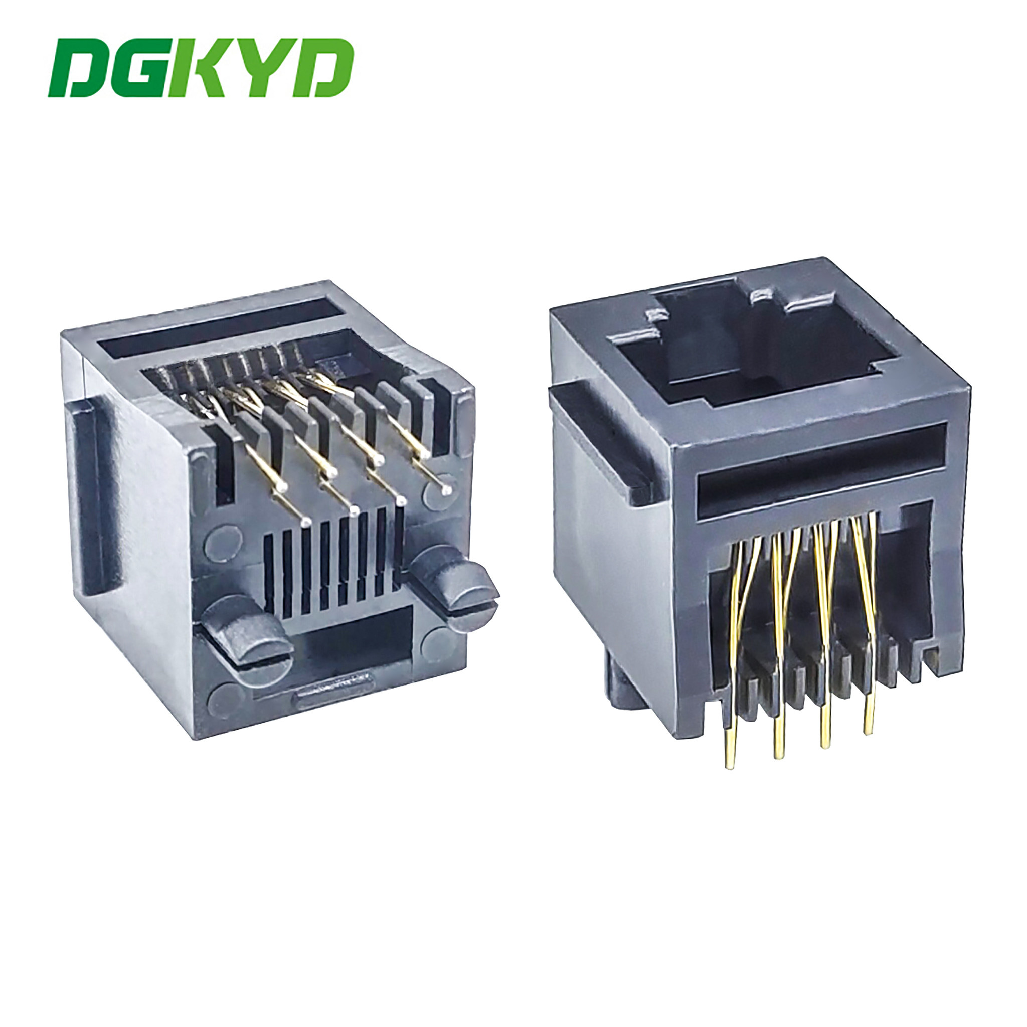
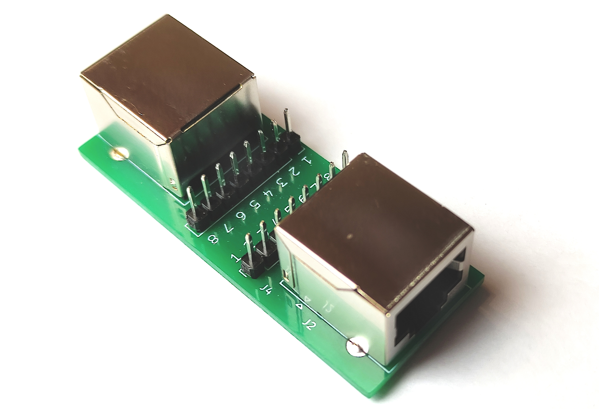
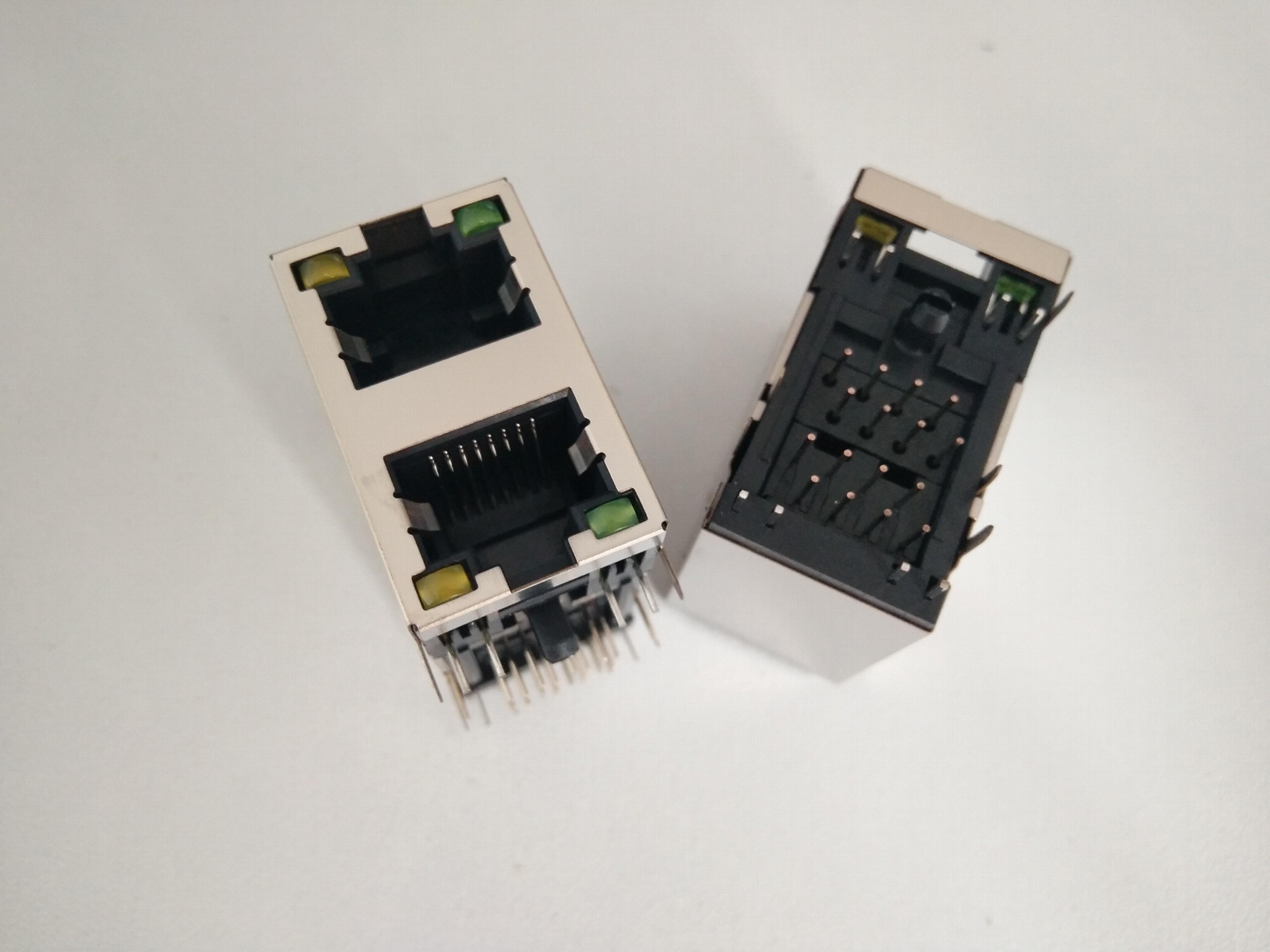
A 1 RJ45 PCB jack is a single-port modular connector designed to be mounted directly onto a printed circuit board (PCB) to provide a physical interface for Ethernet networking. These components serve as the critical bridge between network cabling and the electronic circuitry of devices such as routers, network switches, industrial controllers, and computer peripherals.
Understanding the 1 RJ45 PCB Jack Architecture
The RJ45 (Registered Jack 45) connector is the standardized physical interface for network communications. When referred to as a "PCB jack," it specifically describes a component engineered for through-hole or surface-mount soldering on a rigid circuit board. Unlike modular plugs that terminate cable ends, the PCB jack is a fixed chassis-mount component.
The architecture of a single-port RJ45 PCB jack typically consists of a housing made from high-temperature thermoplastic, copper alloy contact pins plated with gold for conductivity, and, in many models, an integrated magnetic module. The "1" denotes that the housing contains a single port, distinguishing it from ganged or stacked multi-port configurations.
Essential Components and Technical Specifications
When evaluating or selecting a 1 RJ45 PCB jack, engineers must consider several technical factors that determine the reliability and performance of the data connection.
1. Integrated Magnetics vs. Non-Magnetic Jacks
One of the most critical decisions in hardware design is whether to use a "MagJack" or a standard jack.
- Integrated Magnetics: These jacks include transformers and common-mode chokes within the connector housing. They are essential for signal isolation, noise suppression, and protection against high-voltage surges from the Ethernet cable.
- Non-Magnetic Jacks: These are simple physical interfaces. Designers choose these when the magnetics are already placed elsewhere on the PCB or when the application does not require galvanic isolation within the connector body.
2. Mounting Configurations
- Through-Hole (THT): The most common style, where contact pins pass through drilled holes in the PCB. This provides high mechanical strength, which is vital for ports that experience frequent insertion and extraction cycles.
- Surface Mount (SMT): The pins sit on pads on the surface of the PCB. These are favored in high-density, compact electronic designs but generally offer lower physical durability compared to through-hole variants.
3. Shielding and Grounding
Shielded RJ45 jacks feature a metal shroud, usually made of nickel or tin-plated copper alloy, that surrounds the plastic housing. This is crucial for applications susceptible to electromagnetic interference (EMI) or radio frequency interference (RFI). Proper grounding of the shield to the PCB chassis is necessary to effectively dissipate noise.
Applications in Modern Electronics
The 1 RJ45 PCB jack is ubiquitous in environments requiring stable, wired data transmission. As of 2026, despite the dominance of wireless technology, wired connections remain the gold standard for latency-sensitive and high-bandwidth applications.
- Industrial Automation: In factory settings, shielded jacks are used in programmable logic controllers (PLCs) and human-machine interfaces (HMIs) to maintain signal integrity in electrically noisy environments.
- Consumer Networking: Single-port jacks are the primary interface for individual LAN ports on home routers, Wi-Fi access points, and smart home gateways.
- Embedded Systems: Developers of Internet of Things (IoT) devices use compact 1-port jacks to provide scalable wired connectivity for remote sensing and control.
Comparison of RJ45 Mounting and Configuration Types
Selecting the correct jack depends on the physical space available and the electrical requirements of the device.
| Feature | Through-Hole (THT) | Surface Mount (SMT) | Integrated Magnetics |
|---|---|---|---|
| Mechanical Strength | Very High | Moderate | Variable |
| Board Space | Larger footprint | Compact | Depends on design |
| Assembly Speed | Slower (Wave soldering) | Fast (Reflow) | N/A |
| EMI Performance | Standard | Standard | Superior |
Design Considerations and Best Practices
Designing a PCB to accept a 1 RJ45 jack requires careful attention to trace routing and board layout. Poor layout can introduce crosstalk, which degrades the performance of high-speed Ethernet (e.g., 10GBASE-T).
- Differential Pair Routing: Ethernet signals are transmitted via differential pairs. Designers must ensure these traces are of equal length and are routed as close together as possible to maintain impedance matching, typically at 100 ohms.
- Keep-out Zones: Beneath the jack, designers should avoid placing sensitive components or traces, especially if the jack is shielded. Electromagnetic noise can couple into the PCB if the layout is not strictly managed.
- Mechanical Stress: Since the RJ45 jack is a user-facing component, it will be subject to mechanical force. Use "anchor" pins or additional solder points on the metal housing to ensure the jack does not tear the copper pads off the PCB when a cable is tugged or inserted at an angle.
Verification and Troubleshooting
If a system fails to establish a network link, the RJ45 PCB jack is often the first point of inspection. In 2026, standard troubleshooting protocols for these components include:
- Visual Inspection: Check for bent pins (contact deformation) within the jack. Often, repeated use causes the spring-loaded pins to lose their tension, resulting in an intermittent connection.
- Solder Joint Integrity: Inspect the solder fillets on the underside of the PCB. "Cold" solder joints or hairline cracks can form due to thermal expansion and contraction over time.
- Continuity and Impedance Testing: Using a high-bandwidth oscilloscope and a network analyzer, engineers can verify that the differential signal remains within acceptable return-loss parameters.
Frequently Asked Questions (FAQ)
What is the difference between Category 5e and Category 6 RJ45 jacks? The difference lies in the internal construction and the quality of the contact pins. While the physical port size remains the same, Cat6 jacks are manufactured to tighter tolerances to minimize crosstalk, allowing for the higher frequencies required for gigabit and multi-gigabit speeds.
Can I use a shielded jack in an unshielded application? Yes, but you must ensure that the shield is properly managed. If a shielded jack is used but not connected to a grounded chassis or drain wire, the shield can act as an antenna, potentially collecting and radiating EMI, which negatively impacts signal quality.
What causes an RJ45 port to stop working after years of use? The most common cause is metal fatigue of the contact pins or oxidation buildup. The contact points inside the jack are spring-loaded; over years of plugging and unplugging, these springs lose their elasticity. Additionally, dust and debris can prevent full electrical contact between the cable and the jack.
Is it necessary to have integrated magnetics on the PCB? If your Ethernet controller (PHY) does not have integrated magnetic support, then external magnetics are mandatory for safety and signal coupling. Without them, the system will not meet IEEE 802.3 standards and will be highly susceptible to interference.
How do I choose between top-entry and side-entry jacks? This is purely determined by the device enclosure. Side-entry (horizontal) jacks are standard for slim devices like routers, while top-entry (vertical) jacks are used when the port needs to face upward, such as in certain industrial sensors or ceiling-mounted hardware.
Recommendations for Implementation
When integrating a 1 RJ45 PCB jack into your next project, prioritize components from reputable manufacturers that provide detailed 3D models and footprint libraries. If the device will be used in high-vibration or high-traffic areas, opt for through-hole mounting with reinforced housing clips. Always cross-reference the data sheet for the specific magnetic circuit if using a MagJack, as pinouts are not universally standardized across all brands and models.