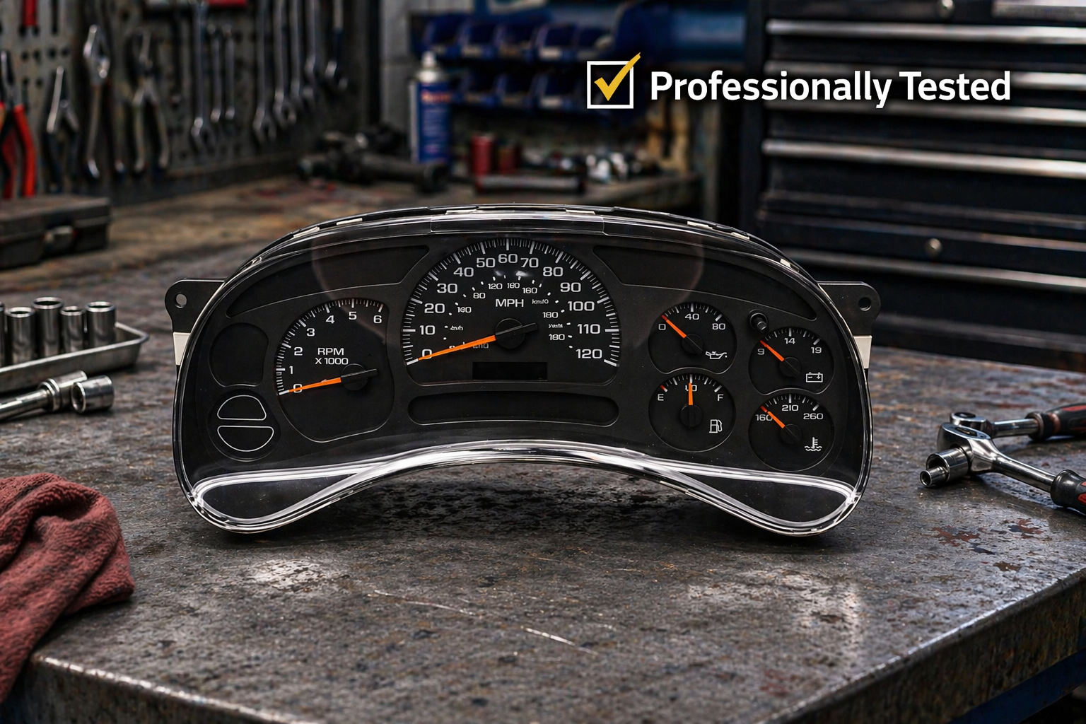
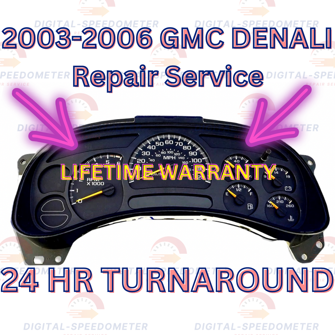
The 2005 GMC Yukon Denali is widely celebrated for its robust performance, luxury appointments, and enduring capability. However, like many General Motors trucks and SUVs built during the mid-2000s, it is plagued by a notorious issue: failing instrument cluster stepper motors. When the speedometer begins to stick, reads inaccurately, drops to zero unexpectedly, or becomes entirely unresponsive, it presents both a frustrating inconvenience and a serious legal and safety hazard. Resolving this problem requires understanding the root cause—specifically, the widespread design flaw in the original air-core stepper motors manufactured by companies like X27 or 5816—and selecting the appropriate repair path, which typically ranges from DIY motor replacement to professional cluster rebuild services.
Understanding the 2005 GMC Denali Instrument Cluster Failure
To successfully execute a 2005 GMC Denali speedometer fix, one must first understand why the failure occurs. The instrument cluster in the 2005 Denali is entirely electronic, communicating with the vehicle's Powertrain Control Module (PCM) and Body Control Module (BCM) via the Class 2 serial data bus. When the vehicle moves, the Vehicle Speed Sensor (VSS) sends data to the transmission and PCM, which translates that information into a data signal for the instrument cluster.
Inside the cluster, tiny electromagnetic stepper motors physically rotate the indicator needles against small internal stops. The original factory stepper motors utilized in 2003 through 2006 GM trucks and SUVs—often part numbers containing the prefix X15 or early iterations of the X27 series—feature delicate internal plastic gears and copper wire windings that are highly susceptible to premature wear, thermal degradation, and electrical resistance spikes.
Over years of heat cycling inside the dashboard, the fine copper coils inside these motors short out or open up, while the tiny plastic shafts bind. Consequently, the speedometer needle may stick at a certain speed, refuse to return to zero when the vehicle is parked, or jitter violently while driving. Because these clusters use individual stepper motors for each gauge (speedometer, tachometer, oil pressure, coolant temperature, fuel level, and voltmeter), a failure in one motor often signals that others are nearing the end of their operational lifespan.
Diagnosing the Speedometer and Cluster Issues
Before tearing into the dashboard or purchasing repair components, a thorough diagnosis is essential to confirm that the problem lies within the instrument cluster itself rather than an external sensor or wiring harness.
Step-by-Step Diagnostic Process
- Verify External Data Sources: Check if other vehicle systems are functioning normally. Does the transmission shift properly? Does the cruise control hold speed? If the transmission shifts fine and cruise control works, the Vehicle Speed Sensor (VSS) and PCM are transmitting accurate data. The problem is isolated entirely to the instrument cluster display.
- Observe Cluster Behavior: Turn the ignition key to the "ON" position without starting the engine (the dashboard self-test mode). Do the needles sweep smoothly to zero, or do they twitch, lag, or sit above zero? A needle resting above zero when the vehicle is off is a textbook indicator of a failed internal stepper motor.
- Test Power and Ground: Use a digital multimeter to verify that the instrument cluster is receiving proper battery voltage and a clean ground through the fuse panel (specifically the instrument cluster fuse). While total power loss usually blanks out the digital odometer and backlighting, intermittent power drops can cause erratic needle behavior.
- Scan for Diagnostic Trouble Codes (DTCs): Plug an OBD-II scanner capable of reading body and chassis codes (U-codes) into the port under the steering column. While standard generic OBD-II scanners only read powertrain (P-codes), advanced scanners can check for communication faults between the PCM and the instrument cluster.
| Diagnostic Finding | Probable Root Cause | Recommended Action |
|---|---|---|
| Speedometer stuck, other gauges work | Individual stepper motor failure | Replace the speedometer stepper motor |
| All gauges dead, odometer dark | Loss of power, blown fuse, or bad ground | Check fuses and cluster wiring harness |
| Erratic bouncing across multiple gauges | Internal circuit board solder joint failure or failing voltage regulator | Re-solder circuit board or professional rebuild |
| Accurate transmission shifts, dead speedometer | Cluster gauge or internal stepper motor | Replace cluster or rebuild unit |
Comparison of Repair Options
Vehicle owners facing a malfunctioning speedometer generally have three distinct pathways to achieve a reliable fix. Each option carries unique trade-offs regarding cost, time, and technical skill requirements.
1. The DIY Stepper Motor Replacement
- Cost: $15 to $40 for tools and replacement motors.
- Skill Level: Intermediate (requires soldering iron and hand tools).
- Time Commitment: 2 to 3 hours.
- Overview: This method involves removing the instrument cluster from the dash, disassembling the plastic housing, de-soldering the old defective stepper motors from the circuit board, and soldering in upgraded replacement motors (such as the updated generations of X27.168 motors). It is the most cost-effective solution for hands-on owners.
2. Professional Mail-In Rebuild Service
- Cost: $80 to $150.
- Skill Level: Beginner (only requires dash removal).
- Time Commitment: 3 to 7 days turnaround time (shipping included).
- Overview: Numerous specialized electronics companies offer mail-in cluster rebuilding. The owner removes the cluster, ships it to the service center, and technicians replace all stepper motors (not just the broken one), upgrade backlighting bulbs to LEDs if desired, and test the unit on a bench simulator before returning it.
3. Purchasing a Remanufactured Cluster
- Cost: $150 to $300+.
- Skill Level: Beginner.
- Time Commitment: Immediate installation upon delivery.
- Overview: Buying a pre-built remanufactured unit eliminates downtime. However, buyers must verify odometer programming. Because mileage is stored electronically inside the cluster's EEPROM chip, a replacement cluster must be professionally programmed to match the vehicle's actual mileage to maintain legal compliance and accurate vehicle records.
Step-by-Step Guide: DIY Instrument Cluster Removal
Removing the instrument cluster from a 2005 GMC Yukon Denali is a straightforward procedure requiring only basic hand tools, primarily a 7mm socket, a ratchet with an extension, and a non-marring plastic trim removal tool.
Required Tools and Materials
- 7mm socket and ratchet
- Flathead screwdriver or plastic trim panel tool
- Soldering iron (temperature-controlled) and fine-gauge electronics solder
- Desoldering pump (solder sucker) or copper solder wick
- Replacement stepper motors (X27.168 or equivalent)
- Flashlight or work light
Removal Procedure
- Disconnect the Battery: Always disconnect the negative battery terminal before working on vehicle electronics to prevent accidental short circuits or triggering airbag warning lights.
- Drop the Steering Column: Lower the steering wheel to its lowest tilt position to maximize clearance. Set the parking brake firmly and shift the gear selector into the lowest gear (1st gear) to provide room for the cluster bezel to clear the shift lever.
- Remove the Trim Bezel: Grip the wood-grain or plastic dash trim bezel surrounding the instrument cluster and radio. Gently pull straight back toward the rear of the vehicle. The bezel is held in by heavy-duty spring clips. Work your way around the edges until all clips release, then maneuver the bezel out of the cabin.
- Unbolt the Cluster: Locate the four 7mm bolts securing the instrument cluster to the dashboard frame—two at the top corners and two at the bottom corners. Remove these bolts and place them safely aside.
- Disconnect the Wiring Harness: Pull the cluster slightly forward away from the dash. Reach behind the unit, locate the main electrical connector plug, squeeze the locking tab, and pull downward to release it. Remove the cluster completely from the vehicle.
Performing the Board-Level Stepper Motor Repair
Once the cluster is removed and brought to a clean workbench, repairing the internal electronics requires precision and patience.
Disassembly and Soldering
- Separate the Housing: Release the plastic tabs holding the clear front lens and the rear housing to the main circuit board. Gently lift away the lens, followed by the black gauge face overlay. Note: Take extreme care not to bend or scratch the delicate gauge needles.
- Remove the Needles: While some technicians advise pulling the needles straight off their shafts, doing so can strip the delicate brass spindles inside the motors. A safer method is to gently twist the needles counterclockwise past their stop point while pulling upward, or use a specialized needle removal fork tool. Mark the resting positions of the needles if necessary, though newer stepper motors have internal stops that reset position upon power-up.
- Access the Circuit Board: Lift the white plastic backing plate and gauge face mask off the printed circuit board (PCB).
- Desolder the Defective Motor: Locate the solder joints on the back of the circuit board corresponding to the failed speedometer motor (each motor has four mounting pins plus electrical contact pins). Apply your soldering iron to each pin while using a solder sucker or copper wick to remove the molten solder until the pin is completely free.
- Install the New Motor: Once all four pins are free, pull the old stepper motor off the front of the board. Insert the new upgraded stepper motor into position, ensuring its pins align perfectly with the through-holes on the PCB.
- Solder Connections: Apply fresh solder to each pin on the back of the circuit board. Ensure clean, shiny solder joints with no bridging between adjacent pins. Use isopropyl alcohol and a cotton swab to clean away any leftover flux residue.
Reassembly and Testing
Reassembling the instrument cluster is essentially the reverse of the disassembly process, but caution must be exercised to ensure physical alignment is correct.
- Snap the white plastic backing plate back onto the circuit board.
- Reinstall the gauge face overlay, ensuring it sits flat without pinching any components.
- Carefully press the indicator needles back onto the motor shafts. Push them on lightly just above the zero stop point.
- Reattach the clear plastic lens, ensuring all housing tabs snap securely into place to keep dust and moisture out of the unit.
- Carry the cluster back to the vehicle, plug in the main electrical wiring harness firmly until the locking tab clicks, and secure the unit with the four 7mm mounting bolts.
- Reinstall the dash trim bezel by pressing it firmly into its spring clips.
- Reconnect the negative battery terminal. Turn the ignition key to the ON position and verify that all needles perform their self-test sweep and rest accurately at zero. Start the engine and take the vehicle for a brief test drive while monitoring the speedometer against a GPS speed reference to ensure absolute accuracy.
Common Mistakes to Avoid During the Repair
Attempting an instrument cluster repair without proper preparation can result in permanent damage to the circuit board or delicate gauge mechanisms. Avoid these frequent pitfalls:
- Overheating the Circuit Board: Using a cheap, high-wattage soldering iron without temperature control can lift the fragile copper traces off the circuit board, rendering the entire cluster unrepairable. Use a regulated iron set to approximately 650°F to 700°F.
- Forcing the Gauge Needles: Yanking the needles straight up without supporting the motor shaft underneath can pull the internal metal spindle right out of the stepper motor rotor, destroying the motor instantly.
- Neglecting the Other Motors: Since all original stepper motors in a 2005 Denali share the same manufacturing vulnerabilities, replacing only the speedometer while leaving the original fuel or oil pressure motors intact is false economy. It is strongly recommended to replace all stepper motors simultaneously while the unit is disassembled.
Frequently Asked Questions
Can I drive my 2005 GMC Denali with a broken speedometer?
Mechanically, the vehicle will drive and shift normally if the VSS and transmission are operating correctly. However, driving without a working speedometer makes it impossible to monitor your speed accurately, exposing you to speeding citations and severe safety risks. Furthermore, your odometer will stop recording mileage accurately, which violates state and federal vehicle maintenance tracking standards.
Do I need to reprogram the odometer when replacing stepper motors?
No. Replacing the physical stepper motors on the circuit board does not affect the EEPROM chip where vehicle mileage data is stored. Your original odometer reading will remain intact and accurate once the cluster is reinstalled and powered up. Reprogramming is only required if you replace the entire instrument cluster assembly with a different used or remanufactured unit.
Are aftermarket stepper motors more reliable than the original ones?
Yes. The replacement stepper motors widely available today—such as the revised versions of the X27.168 series—feature redesigned internal metal gears and improved copper coil windings that overcome the thermal breakdown issues inherent in the original factory equipment.
Why do all GM gauges fail around the same era (2003–2006)?
General Motors sourced instrument cluster motors during this period from suppliers that utilized a specific batch of air-core stepper motors with vulnerable internal components. Combined with the high ambient heat inside closed truck dashboards during summer months, the internal copper wire insulation breaks down over time, causing electrical resistance failures across millions of vehicles from this production era.
How much does it cost to have a professional fix the speedometer?
If you remove the cluster yourself and send it to a mail-in repair service, expect to pay between $80 and $150 including return shipping. If you take the vehicle to a specialized automotive electronics shop or dealership where they handle the removal and reinstallation labor as well, the total cost typically ranges from $250 to $450.
Conclusion and Next Actions
Fixing the speedometer on a 2005 GMC Denali restores essential driving safety, eliminates dashboard anxiety, and preserves the proper operation of your luxury SUV. Whether you choose to invest in a complete professional mail-in rebuild or tackle the soldering work yourself with a set of upgraded replacement stepper motors, addressing the root cause rather than applying a temporary patch is the key to a permanent repair. Begin by testing your vehicle's speed data signals to confirm the fault is isolated to the cluster, gather the necessary soldering tools or select a reputable repair vendor, and restore full functionality to your dashboard today.