Arduino RFID modules, primarily the MFRC522, allow microcontrollers to communicate with contactless tags using Radio Frequency Identification (RFID) technology at a 13.56 MHz frequency. To use these modules, you interface them via the Serial Peripheral Interface (SPI) protocol, install dedicated libraries, and program the Arduino to identify the Unique Identifier (UID) of various tags to trigger specific hardware actions or data logs.
Understanding the Fundamentals of RFID Technology
Radio Frequency Identification (RFID) is a wireless communication method that utilizes electromagnetic fields to identify and track tags attached to objects. Unlike barcodes, which require a direct line of sight to be scanned, RFID tags only need to be within a certain proximity to a reader to transmit data. This makes the technology ideal for automation, security, and inventory management.
In the context of Arduino hobbyist electronics, we primarily deal with Passive RFID. This means the tags do not have their own power source (like a battery). Instead, they are powered by the electromagnetic field generated by the RFID reader module. When a tag enters this field, its internal antenna picks up the energy, powers up the integrated circuit (IC) inside the tag, and reflects a signal back to the reader with its stored information.
There are three main frequency ranges used in RFID:
- Low Frequency (LF): 125 kHz – 134 kHz. These have a short read range and are often used for animal tracking or basic building access.
- High Frequency (HF): 13.56 MHz. This is the frequency used by the popular MFRC522 module and most Near Field Communication (NFC) devices. It offers a balance of range and data transfer speed.
- Ultra-High Frequency (UHF): 860 MHz – 960 MHz. These are used in industrial logistics for reading hundreds of tags simultaneously from several meters away.
For the purpose of "basics," we focus on the HF 13.56 MHz spectrum, as it is the most accessible for Arduino users and provides the best documentation for beginners.
The MFRC522 RFID Module: Features and Specifications
The MFRC522 is the standard entry-point module for Arduino RFID projects. Produced by NXP Semiconductors, this chip is highly integrated and supports various contactless communication methods. When you purchase an RFID "kit" for Arduino, it almost always includes this blue or red rectangular board, a card-style tag, and a keychain-style fob.
Key Technical Specifications
Understanding the electrical limits of the MFRC522 is crucial to avoid damaging the hardware.
- Operating Voltage: 2.5V to 3.3V. This is a critical point; while the Arduino Uno operates at 5V, the MFRC522 is a 3.3V device.
- Communication Interface: Serial Peripheral Interface (SPI). It can also support I2C and UART, but the vast majority of Arduino libraries are written for SPI.
- Max Data Rate: 10 Mbit/s.
- Read Range: Approximately 0 cm to 5 cm, depending on the antenna quality and tag size.
- Current Consumption: 13–26mA during active reading, with a very low-power "hard power down" mode of about 10µA.
Supported Tag Types
The MFRC522 is designed to work with ISO/IEC 14443 A/MIFARE cards. This includes the MIFARE Classic 1K and 4K, MIFARE Ultralight, and MIFARE DESFire. It is important to note that it cannot read 125 kHz tags or HID Prox cards used in older corporate office buildings.
Hardware Interface and Wiring Logistics
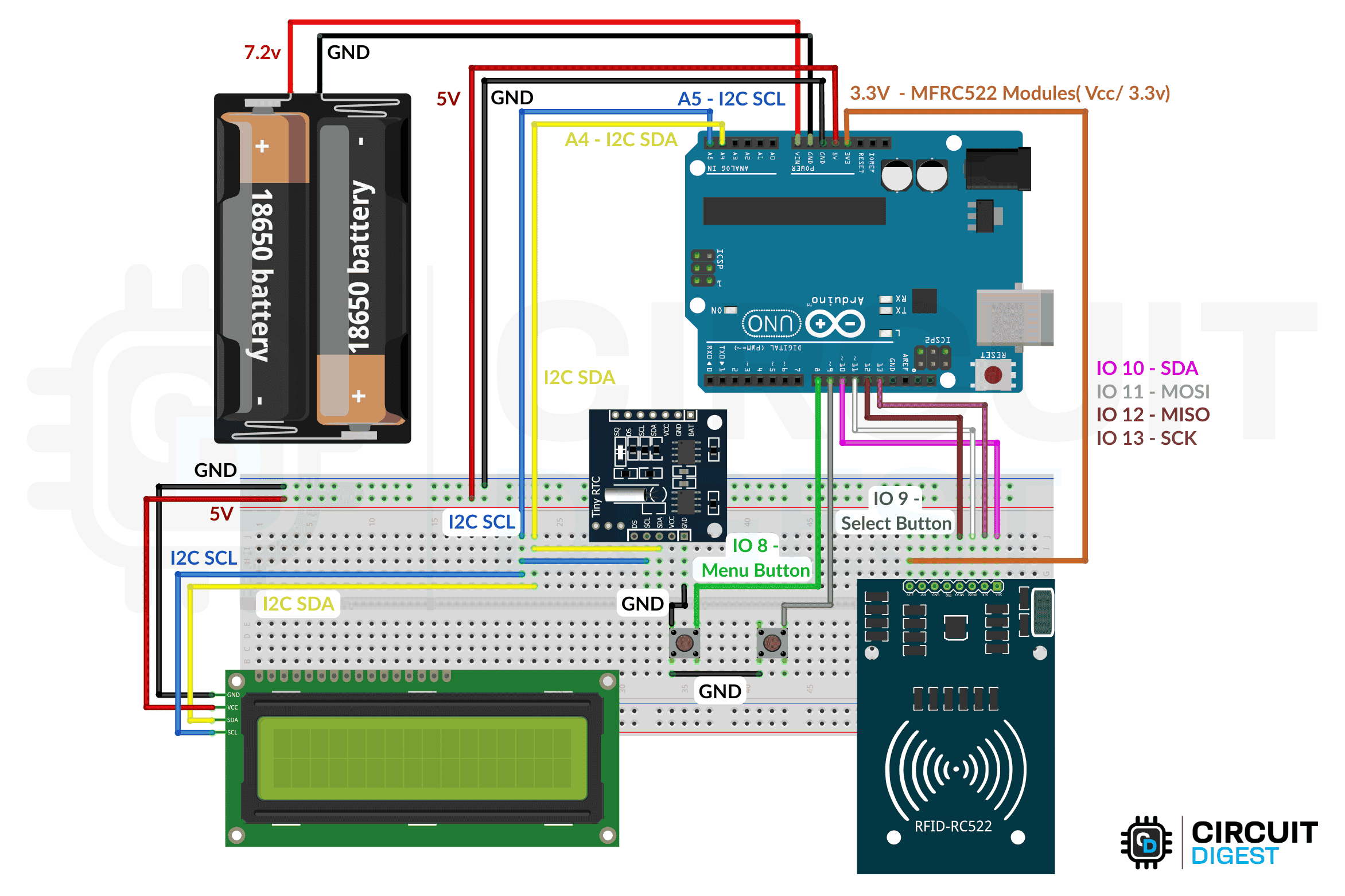
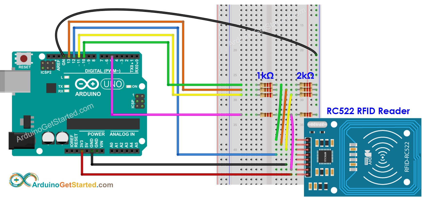
Connecting the MFRC522 to an Arduino requires attention to the SPI bus. SPI is a synchronous serial data protocol used by microcontrollers for communicating with one or more peripheral devices over short distances. It uses four specific pins: MOSI, MISO, SCK, and SS (Slave Select).
The 3.3V Power Constraint
The most common mistake beginners make is connecting the VCC pin of the RFID module to the 5V pin of the Arduino. While the MFRC522 might survive for a few minutes, the heat will eventually destroy the chip. Always use the 3.3V pin. Additionally, while the MFRC522 logic pins are generally considered "5V tolerant" by many in the community, it is best practice to use a logic level shifter if you are building a long-term, stable project to prevent the 5V signals from the Arduino from stressing the 3.3V module.
Standard Pinout for Arduino Uno
| MFRC522 Pin | Arduino Uno Pin | Function |
|---|---|---|
| VCC | 3.3V | Power Supply (Do NOT use 5V) |
| RST | Pin 9 | Reset Pin (Can be changed in code) |
| GND | GND | Ground |
| IRQ | Not Connected | Interrupt Request (Rarely used for basics) |
| MISO | Pin 12 | Master In Slave Out |
| MOSI | Pin 11 | Master Out Slave In |
| SCK | Pin 13 | Serial Clock |
| SDA (SS) | Pin 10 | Slave Select (Default) |
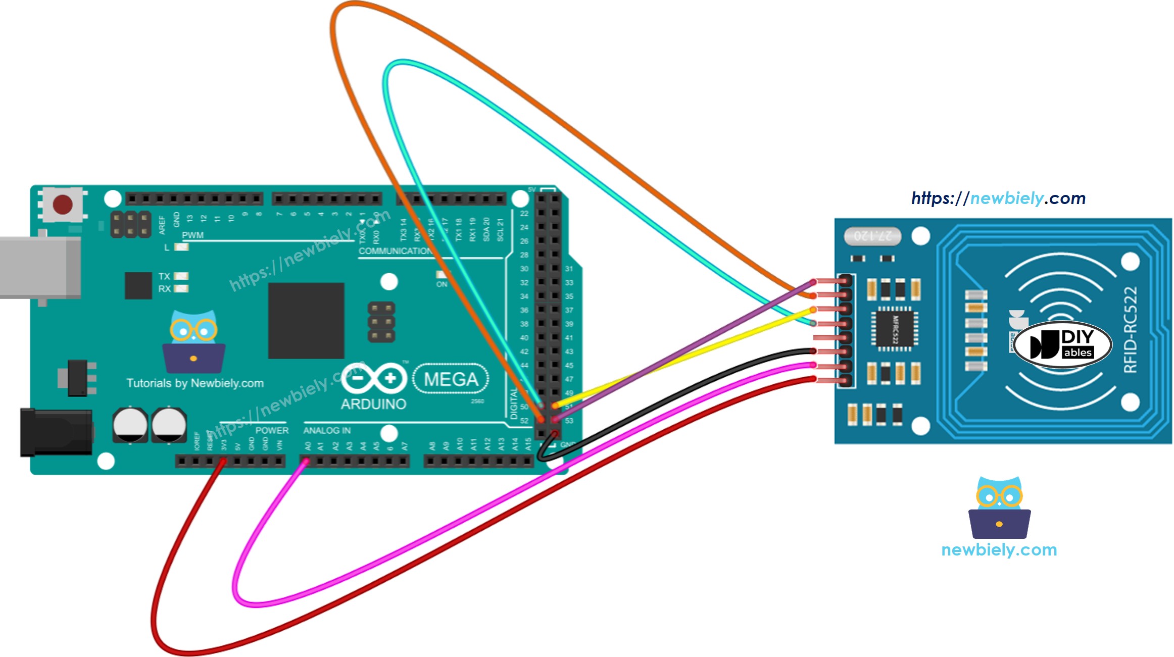
On an Arduino Mega, the SPI pins are different (50 for MISO, 51 for MOSI, 52 for SCK, and 53 for SS). Always check the pinout diagram for your specific board.
Software Requirements and Library Installation
To interact with the MFRC522, you don't need to write the complex timing protocols from scratch. The community has developed robust libraries that handle the "heavy lifting" of the SPI communication and the MIFARE protocol.
The most widely used library is the MFRC522 library by miguelbalboa. You can install this directly through the Arduino IDE:
- Open the Arduino IDE.
- Go to Sketch -> Include Library -> Manage Libraries...
- Search for "MFRC522".
- Select the one by "github/miguelbalboa" and click Install.
Once installed, the library provides several example sketches. The DumpInfo sketch is the best place to start, as it scans a tag and prints every piece of data stored on it to the Serial Monitor, including the UID and the memory block contents.
Core Logic: Reading a Tag's UID
Every RFID tag has a Unique Identifier (UID). For MIFARE Classic tags, this is usually a 4-byte or 7-byte number assigned by the manufacturer. In most basic Arduino projects (like a door lock), the code does not read the actual data stored in the memory blocks; instead, it simply looks at the UID and asks, "Is this UID in my authorized list?"
The Read Sequence
The software logic for reading a card typically follows these steps:
- Initialize SPI and MFRC522: The code starts the SPI bus and the MFRC522 chip.
- Check for Card Presence: The function
PICC_IsNewCardPresent()checks if a tag has entered the electromagnetic field. - Read the Serial: The function
PICC_ReadCardSerial()attempts to read the data from that specific tag. - Extract UID: The code loops through the
uid.uidBytearray to format the UID into a readable string or hex value. - Comparison: The extracted UID is compared against a hardcoded "Master UID."
- Action: If they match, a relay or LED is activated. If not, access is denied.
Advanced Basics: Reading and Writing Data
Beyond the UID, MIFARE tags contain storage. A standard MIFARE Classic 1K card has 1,000 bytes of data storage organized into Sectors and Blocks.
- There are 16 sectors.
- Each sector has 4 blocks.
- Each block contains 16 bytes of data.
To read or write to these blocks, you must handle Authentication. Each sector is protected by two keys: Key A and Key B. By default, most new tags are shipped with these keys set to 0xFFFFFFFFFFFF. If you want to store a person's name or a balance of "credits" on a card, your Arduino code must first authenticate the sector using the correct key before the MFRC522 chip will permit a read or write command.
Comparison of Common Arduino RFID/NFC Modules
| Feature | MFRC522 (Standard) | PN532 (Advanced) | RDM6300 (Legacy) |
|---|---|---|---|
| Frequency | 13.56 MHz | 13.56 MHz | 125 kHz |
| Primary Use | Access Control / Basics | Mobile Phone NFC / P2P | Simple ID Tags |
| Interfaces | SPI (mostly) | SPI, I2C, UART | UART (Serial) |
| NFC Support | Limited | Full (Read/Write/Emulate) | None |
| Operating Voltage | 3.3V | 3.3V to 5V | 5V |
| Complexity | Moderate | High | Low |
Practical Project Implementation: Digital Door Lock
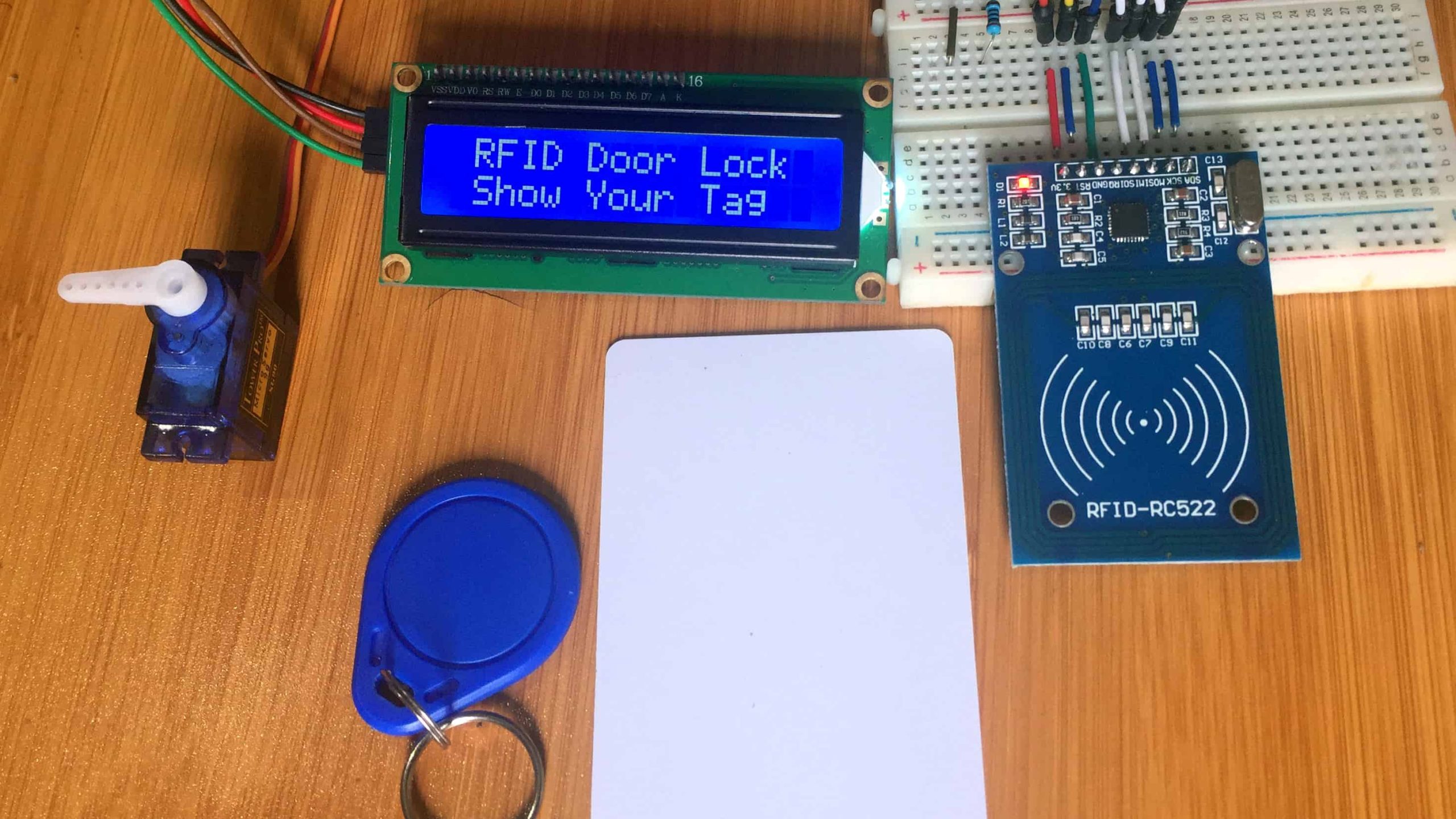
The most common application for "Arduino RFID basics" is the electronic lock. In this setup, the Arduino is paired with an MFRC522 and a 5V Relay module. The relay controls a 12V Solenoid Bolt.
When an authorized card is tapped:
- The Arduino identifies the UID.
- It sends a
HIGHsignal to the relay. - The relay completes the circuit for the solenoid.
- The bolt retracts for 5 seconds and then locks again.
This project introduces the concept of state management. You must ensure the code doesn't "freeze" while waiting for a card, and that it handles "unauthorized" cards gracefully without crashing.
Troubleshooting Common Issues
Even with a simple setup, users often encounter hurdles. Here are the most common solutions:
- "MFRC522 Software Version: 0x0 (unknown)": This error in the Serial Monitor almost always indicates a wiring issue. Check your SPI pins. If the Arduino cannot communicate with the chip, it cannot read the version number. Ensure MISO/MOSI are not swapped.
- Intermittent Reading: If the module only reads cards when they are touching the antenna, check your power supply. RFID modules require a stable current. If the Arduino is powered by a weak USB port, the electromagnetic field might be too weak.
- Tag Not Detected: Ensure you are using 13.56 MHz tags. 125 kHz tags (often thick plastic cards) will not react to the MFRC522 field.
- Library Conflicts: If you have multiple RFID libraries installed, the Arduino IDE may include the wrong header file. It is best to keep only the Miguel Balboa library if you are a beginner.
Security Considerations in 2026
While the MFRC522 and MIFARE Classic 1K tags are excellent for learning, they are not considered "high security" in 2026. The MIFARE Classic encryption (Crypto-1) was cracked years ago. Tools now exist that can "sniff" the communication and clone these cards in seconds using a smartphone or specialized hardware like a Flipper Zero.
For learning the basics, these modules are perfect. However, if you are designing a lock for a high-value area or a front door, you should eventually progress to MIFARE DESFire tags or NTAG21x series tags, which offer significantly better encryption and are harder to clone.
Frequently Asked Questions
Can I use the MFRC522 to read my credit card or smartphone?
While both credit cards and smartphones use 13.56 MHz, they use advanced encryption and dynamic UIDs for security. The MFRC522 may detect a "presence," but it will usually see a different UID every time you tap your phone (due to MAC randomization and tokenization), making it useless for standard "Master UID" authentication projects.
How many tags can I store in the Arduino's memory?
The Arduino Uno has limited SRAM (2KB). If you are only storing UIDs (which are typically 4 to 7 bytes), you can easily store dozens or even a hundred authorized IDs in the code. For larger databases, you would need to use the Arduino's EEPROM or an external SD card module.
What is the maximum distance for reading a tag?
For the MFRC522, the practical limit is about 3 to 5 centimeters. If you place the reader behind a thick wooden panel or plastic enclosure, the range will decrease. Metal surfaces will interfere with the electromagnetic field and may prevent reading entirely unless you use specialized "on-metal" RFID tags.
Can I connect two RFID readers to one Arduino?
Yes. Since the MFRC522 uses SPI, you can connect multiple modules to the same MOSI, MISO, and SCK pins. You simply need to assign a unique SDA (SS) and RST pin to each module. In your code, you would then create two separate MFRC522 instances and poll them sequentially.
Does the MFRC522 work with ESP32 or ESP8266?
Yes, it works very well with these boards. However, you must be careful with pin assignments, as the SPI pins on an ESP32 (VSPI or HSPI) differ from the Arduino Uno. Since ESP32 boards are natively 3.3V, they are actually a safer match for the MFRC522 than the 5V Arduino Uno.
Next Steps for Beginners
After mastering the basics of reading a UID and triggering an LED, the next logical step is to integrate a 16x2 LCD screen to display personalized greetings based on the tag identified. Following that, exploring the write capabilities to create a simple "pre-paid card" system will deepen your understanding of hex data structures and authentication keys.