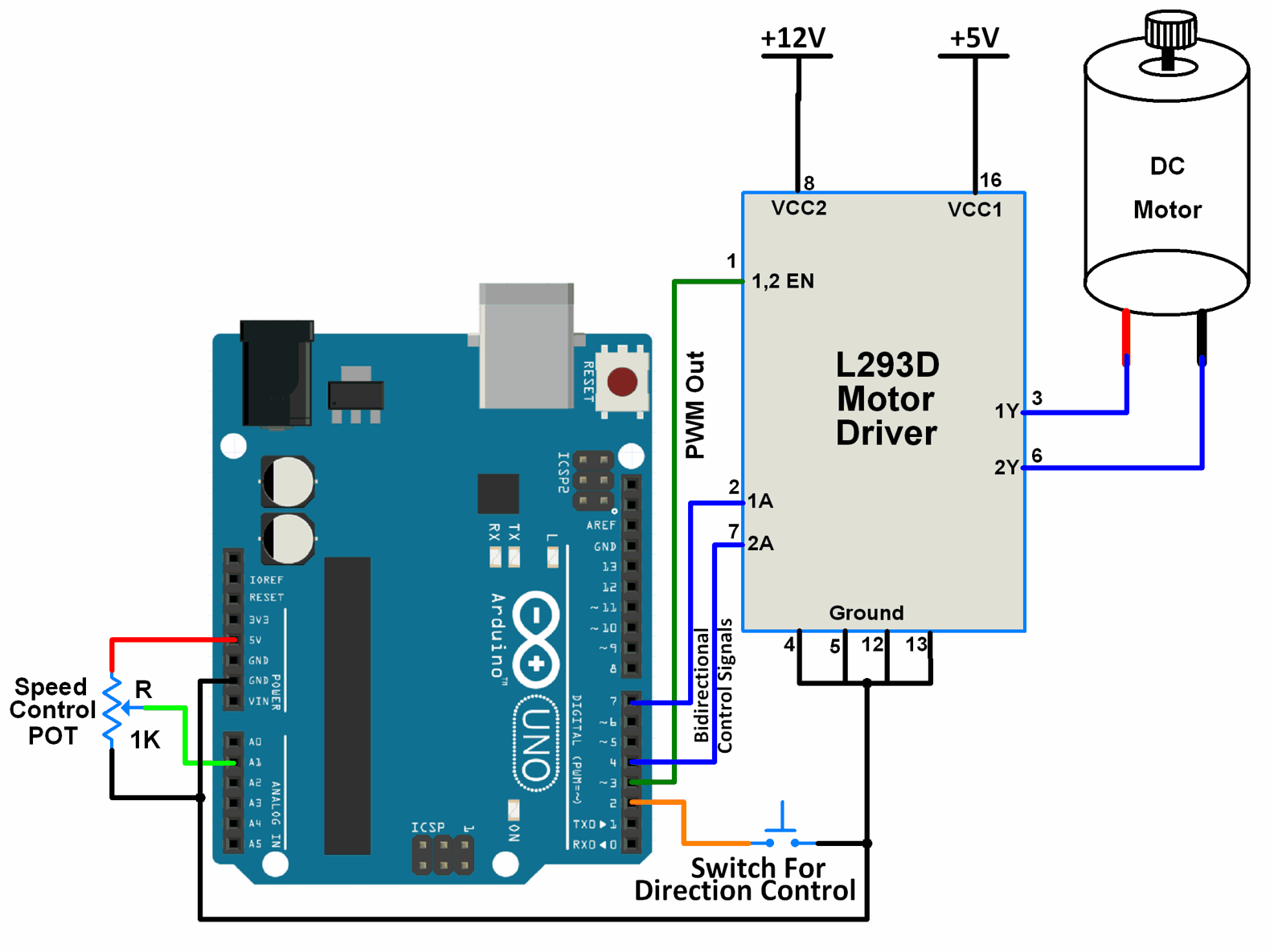
Controlling the speed and direction of a DC motor using an Arduino is primarily achieved through Pulse Width Modulation (PWM). By rapidly toggling a digital output pin between high and low states, the Arduino simulates a variable analog voltage. This technique, combined with an H-bridge motor driver, allows for precise manipulation of motor RPM and rotation without the significant power loss associated with linear voltage regulation.
The Fundamentals of Pulse Width Modulation (PWM)
Pulse Width Modulation is a sophisticated method of delivering power to electrical devices. In the context of motor control, PWM works by switching the power supply on and off at a very high frequency. The "perceived" voltage received by the motor is the average value of these on-off pulses over time.
The most critical concept in PWM is the Duty Cycle. The duty cycle is the percentage of time that the signal remains in a "high" (on) state during a single pulse period. For example, if a signal is high for 1 millisecond and low for 1 millisecond, the total period is 2 milliseconds, and the duty cycle is 50%. On a standard 5V Arduino, a 50% duty cycle yields an effective average voltage of 2.5V. If the duty cycle is increased to 75%, the motor receives an average of 3.75V, causing it to spin faster. Conversely, a 25% duty cycle results in 1.25V, slowing the motor down.
In 2026, while many high-end industrial controllers use specialized DACs (Digital-to-Analog Converters), the Arduino’s use of PWM remains the industry standard for hobbyist and mid-tier prototyping due to its efficiency. Because the controlling transistor (inside a motor driver) is either fully on or fully off, it spends very little time in the intermediate state where resistance—and therefore heat—is highest. This makes PWM significantly more efficient than using a variable resistor or a linear regulator to control motor speed.
Arduino Hardware Capabilities and PWM Pins
Not every pin on an Arduino board is capable of PWM. When designing a circuit, it is essential to identify the pins marked with a tilde (~) symbol on the silkscreen of the board.
On the classic Arduino Uno, which remains a foundational tool in 2026, PWM is available on pins 3, 5, 6, 9, 10, and 11. These pins are driven by internal timers within the ATmega328P microcontroller.
- Pins 5 and 6: These are controlled by Timer 0. Because Timer 0 is also responsible for the Arduino's internal timing functions (like the millis and delay functions), these pins operate at a slightly higher frequency of approximately 980 Hz.
- Pins 3, 9, 10, and 11: These pins operate at approximately 490 Hz.
When using the Arduino Mega, users have access to significantly more PWM pins (pins 2 through 13 and 44 through 46), which is ideal for complex robotics projects requiring multiple motors and actuators. The Arduino Uno R4, featuring a 32-bit Renesas RA4M1 microprocessor, offers enhanced PWM resolution and flexibility compared to the 8-bit R3, though the fundamental programming logic remains consistent.
The core function used to control these pins is analogWrite(pin, value). Despite its name, this function does not produce a true analog voltage; rather, it sets the duty cycle for the PWM signal. The value parameter is an 8-bit integer ranging from 0 to 255. A value of 0 results in a 0% duty cycle (always off), while a value of 255 results in a 100% duty cycle (always on).
The Necessity of Motor Drivers and H-Bridges
A common mistake among beginners is attempting to connect a DC motor directly to an Arduino pin. Arduino digital pins are designed for logic signaling, not power delivery. A standard Arduino pin can typically provide only 20mA to 40mA of current. Most DC motors require hundreds of milliamps or even several amperes to start and run under load. Connecting a motor directly can draw too much current, permanently damaging the microcontroller's internal circuitry.
To solve this, a Motor Driver acts as an intermediary. It takes the low-current PWM signal from the Arduino and uses it to switch a high-current power source connected to the motor.
The most common architecture for a motor driver is the H-Bridge. An H-bridge is a circuit consisting of four switches (usually MOSFETs or BJTs) arranged in an "H" shape around the motor. By closing specific pairs of switches, the driver can reverse the polarity of the voltage applied to the motor, allowing it to spin both clockwise and counter-clockwise.
Common motor driver modules in use as of 2026 include:
- L298N: A rugged, though older, dual H-bridge driver capable of handling up to 2A per channel. It is known for its large heat sink and high voltage drop.
- TB6612FNG: A more modern, efficient MOSFET-based driver that provides better performance and generates less heat than the L298N in a much smaller form factor.
- L293D: Often found in "motor shields," this is a quad half-H driver suitable for smaller, low-current motors.
- BTS7960: A high-current driver used for heavy-duty applications, capable of handling up to 43A, making it suitable for large-scale robotics.
Wiring and Circuit Integration
Proper wiring is critical to prevent electrical interference and hardware failure. A standard PWM motor control setup requires three main components: the Arduino, the motor driver, and an external power supply (such as a LiPo battery or a DC wall adapter).
Common Grounding: The most vital rule in wiring is that the Arduino ground (GND) must be connected to the motor driver's ground. Without a shared reference point, the PWM signals from the Arduino will be "floating" relative to the driver, leading to erratic motor behavior or a complete failure to respond.
Logic vs. Load Power: Most motor drivers have separate pins for logic power (Vcc) and motor power (Vm or V-pin). The logic power (typically 5V) powers the internal chips of the driver, while the motor power (which can be 7V, 12V, or 24V depending on the motor) is what actually turns the shaft. Never attempt to power a motor from the Arduino’s 5V or 3.3V pins, as this will likely cause the Arduino to brown out or reset.
Signal Pins: To control a single motor with speed and direction, you typically need three pins on the Arduino:
- Enable Pin (PWM): Connected to a PWM-capable pin on the Arduino. This controls the speed.
- Input 1: Connected to a standard digital pin.
- Input 2: Connected to another standard digital pin.
By setting Input 1 to HIGH and Input 2 to LOW, the motor spins in one direction. Reversing them (LOW/HIGH) reverses the motor. Setting both to LOW stops the motor. The speed is dictated by the analogWrite value sent to the Enable pin.
Software Logic and Implementation
Programming the Arduino for PWM control involves defining the pin modes and using conditional logic to set the speed and direction.
In the setup section of the code, all three pins (Enable, Input 1, and Input 2) must be configured as OUTPUT using the pinMode function. In the loop section, the user defines the desired behavior. For instance, to move a robot forward at half-speed, the code would set the direction pins to the forward state and then call analogWrite(enablePin, 127).
It is best practice to implement a "ramp-up" or "ramp-down" logic in more complex 2026 applications. Abruptly switching a motor from full speed to a stop or full reverse can create significant back-EMF (Electromotive Force) and mechanical stress. By using a simple for-loop to gradually increase the PWM value from 0 to 255, you can ensure smoother operation and longevity of the mechanical components.
Technical Comparison of Popular Motor Driver Modules
The following table compares the specifications of common motor drivers used with Arduino boards.
| Driver Module | Max Continuous Current | Peak Current | Operating Voltage | Switching Type | Recommended Use Case |
|---|---|---|---|---|---|
| L298N | 2.0A | 3.0A | 5V - 35V | Bipolar (BJT) | Education and large hobby robots. |
| L293D | 0.6A | 1.2A | 4.5V - 36V | Bipolar (BJT) | Small toy motors and solar projects. |
| TB6612FNG | 1.2A | 3.2A | 4.5V - 15V | MOSFET | Battery-powered portable robotics. |
| DRV8833 | 1.2A | 2.0A | 2.7V - 10.8V | MOSFET | Low-voltage, high-efficiency apps. |
| BTS7960 | 43A | 60A | 6V - 27V | MOSFET | Heavy-duty carts and power tools. |
| Cytron 10A | 10A | 30A | 5V - 30V | MOSFET | Combat robotics and CNC machines. |
Advanced Considerations: Frequency and Noise
While the default PWM frequencies of 490 Hz and 980 Hz are sufficient for most DC motors, they sometimes produce a high-pitched "whining" noise. This occurs because the frequency is within the range of human hearing, and the motor's internal coils vibrate at that frequency.
In advanced 2026 projects, developers often modify the Arduino's timer registers to increase the PWM frequency to ultrasonic levels (above 20 kHz). This eliminates the audible noise and can lead to smoother motor performance, although it requires a deeper understanding of the microcontroller's datasheet. However, increasing the frequency also increases the switching losses in the motor driver, meaning the driver may run slightly hotter.
Another critical consideration is Electromagnetic Interference (EMI). Motors are "noisy" devices electrically. As the brushes inside a DC motor spin, they create tiny sparks that generate radio-frequency interference. This noise can travel back through the power lines and cause the Arduino to crash or sensors to give false readings. To mitigate this:
- Solder a small ceramic capacitor (0.1µF) across the motor terminals.
- Keep motor power wires twisted together to cancel out magnetic fields.
- Use a separate battery for the motors and the Arduino if possible.
Troubleshooting Common PWM Issues
If the motor is not spinning as expected, the issue usually falls into one of three categories: power, wiring, or logic.
Motor Whining but Not Spinning: This is usually a sign that the PWM duty cycle is too low to overcome the motor's static friction, or the power supply does not have enough current to start the motor. Increase the analogWrite value or check if the power supply can handle the motor's stall current.
Motor Spins Only in One Direction: This typically indicates a wiring error on one of the input pins or a blown channel on the H-bridge driver. Check the continuity of the signal wires between the Arduino and the driver.
Arduino Resets When Motor Starts: This is a classic power surge issue. When a motor starts, it draws a massive amount of current (stall current), which can cause the voltage to drop momentarily. Adding a large electrolytic capacitor (100µF to 1000µF) across the motor driver's power input can act as a buffer and prevent these brownouts.
Frequently Asked Questions
Can I use PWM to control a brushless DC motor (BLDC)?
No, standard DC motor drivers and the analogWrite function are intended for brushed DC motors. Brushless motors require Electronic Speed Controllers (ESCs), which interpret a different type of signal (Pulse Width Modulation but specifically formatted as a Servo signal) to manage the complex three-phase timing required for BLDC rotation.
What is the difference between PWM and a variable resistor?
A variable resistor (potentiometer) controls speed by dissipating excess energy as heat, which is highly inefficient and can burn out the resistor at high currents. PWM controls speed by switching the power on and off very fast, which wastes almost no energy and allows the motor to maintain higher torque even at lower speeds.
Why do some Arduino pins have different PWM frequencies?
This is due to the way the ATmega328P hardware timers are mapped. Pins 5 and 6 are linked to Timer 0, which also handles system timing. To maintain accuracy for functions like delay(), Timer 0 runs at a different prescaler than Timer 1 (pins 9 and 10) or Timer 2 (pins 3 and 11).
Do I need a flyback diode for my PWM setup?
Most modern motor driver modules (like the L298N or TB6612) have built-in flyback diodes to protect against voltage spikes generated by the motor's inductive load. However, if you are building your own H-bridge from discrete transistors, you must include flyback diodes to prevent the back-EMF from destroying your transistors.
Can I control a 12V motor with a 5V Arduino using PWM?
Yes. The Arduino provides the 5V logic signal (PWM) to the motor driver. The motor driver then switches the 12V supply to the motor. The Arduino and the motor do not need to share the same voltage, but they must share the same ground.
Final Recommendations for Your Project
For most beginners and intermediate makers in 2026, the TB6612FNG is the recommended motor driver for small to medium projects due to its efficiency and compact size. When implementing PWM, always start with a low PWM value and gradually increase it to test the mechanical limits of your system.
Always ensure your power source is rated for at least 20% more current than the total stall current of all motors in your system combined. By following these principles of shared grounding, proper driver selection, and EMI mitigation, you can build robust and precise motion control systems for any robotic application.