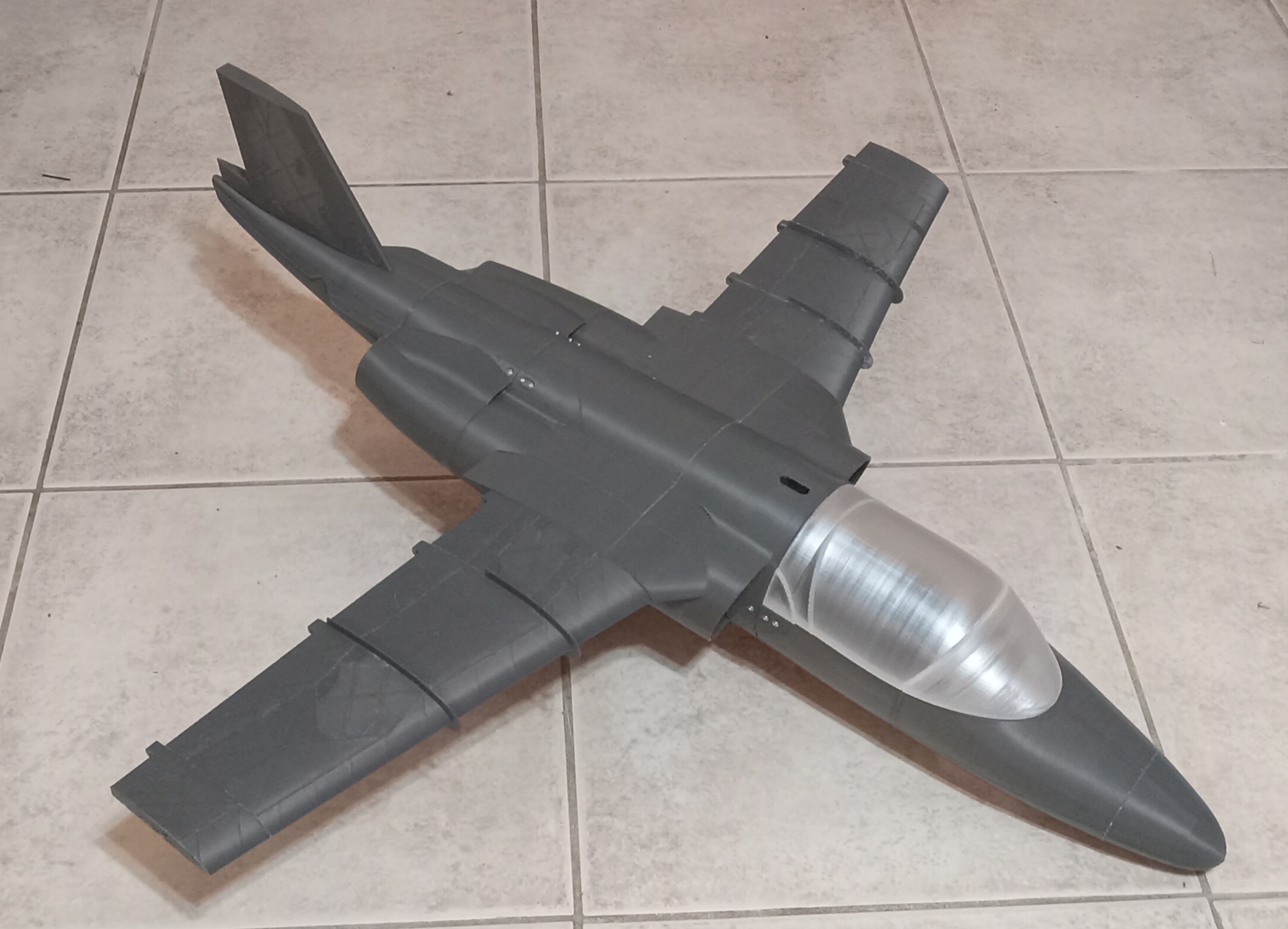
Designing a quiet, custom, experimental electric ducted fan (EDF) using 3D printing requires balancing aerodynamic efficiency, structural integrity under high centrifugal loads, and acoustic optimization. By leveraging desktop fused deposition modeling (FDM) or stereolithography (SLA) printing alongside advanced blade-element momentum theory, makers can prototype unconventional shroud geometries and multi-bladed rotors tailored to suppress high-frequency whining without sacrificing static thrust.
Understanding EDF Acoustic Signatures and Experimental Shroud Design
The distinctive, high-pitched scream of a traditional electric ducted fan stems primarily from the interaction between rotor tip vortices, stator wake interference, and blade passing frequency (BPF). When a rotor blade spins at upwards of 35,000 RPM inside a close-fitting cylindrical duct, pressure waves strike the inner wall and propagate outward. In experimental acoustic engineering, mitigating this noise profile requires a radical departure from off-the-shelf commercial designs.
Custom 3D printed EDF projects allow enthusiasts to experiment with variable-clearance ducts, acoustic liners, and non-axisymmetric exhaust geometries. Because FDM and resin printers can reproduce complex internal channels that are impossible to machine via traditional CNC methods without multi-axis setups, makers can integrate Helmholtz resonators or slotted acoustic bypass liners directly into the duct wall. However, translating these theoretical dampening structures into physical prints introduces severe mechanical hurdles, particularly regarding centripetal stress, thermal softening, and layer adhesion fatigue.
Aerodynamic Fundamentals of Ducted Fans
Unlike free-propeller systems, an EDF relies on a ducted shroud to augment thrust by accelerating mass flow through a converging-diverging profile. The fan unit acts as a high-pressure compressor stage.
- Rotor-Stator Interaction: Spacing between the rotating blades and the stationary straightening vanes is a critical acoustic variable. Placing stators too close to the rotor creates intense pressure pulses, amplifying discrete frequency spikes.
- Tip Clearance Losses: In 3D printed setups, warping or layer inaccuracies can widen the gap between blade tips and the duct wall, causing localized stall and turbulent whistling.
- Blade Count Optimization: Moving from standard 3- or 5-blade configurations to higher blade counts (e.g., 9, 11, or 12 blades) shifts the blade passing frequency higher into a range that is less piercing to the human ear and more easily attenuated by damping materials.
Material Science and 3D Printing Parameters for High-RPM Rotors
Spinning a 3D printed rotor at tens of thousands of RPM places extreme demands on thermoplastic polymers and photopolymer resins. Centrifugal forces scale quadratically with rotational speed, meaning a minor imbalance can instantly shatter a printed impeller, turning it into shrapnel.
Selecting the appropriate printing technology and filament chemistry is the single most important safety and performance decision in a custom EDF build. Standard polylactic acid (PLA) is wholly unsuited for operational EDF rotors due to its low glass transition temperature ($T_g \approx 60^\circ C$), which causes the blades to deform under aerodynamic loads and motor heat.
Comparison of Printing Technologies and Materials
| Material / Technology | Tensile Strength | Thermal Resistance ($T_g$) | Suitability for Rotors | Suitability for Shrouds |
|---|---|---|---|---|
| PLA / FDM | Moderate | Poor (~60°C) | Unsafe (Deforms/Shatters) | Acceptable for low-power tests |
| PETG / FDM | Good | Moderate (~80°C) | Marginal (Prone to creep) | Good (Durable, easy to print) |
| Carbon Fiber Nylon / FDM | Excellent | High (120°C+) | Recommended (High stiffness) | Excellent (Resists hoop stress) |
| Engineering Resin / SLA | High Rigidity | Moderate (~70-90°C) | Excellent for complex blade geometry | Poor (Brittle under impact) |
Slicer Settings for Structural Integrity
When slicing a custom experimental rotor, standard profile settings will lead to catastrophic failure.
- Perimeters/Walls: Set perimeters to 4 or more to ensure solid load paths from the root to the tip of each blade. Avoid sparse infill in thin blades; instead, use 100% rectilinear or gyroid infill, or model the blades as solid volumetric shells in CAD.
- Orientation: Print rotors flat on the build plate (bed-adhesion dependent) or vertically depending on the layer shear vectors. For FDM, printing rotors flat minimizes the risk of delamination along the z-axis caused by centrifugal pull, provided layer adhesion is optimized via high nozzle temperatures and enclosed chambers.
- Dynamic Balancing: Post-processing is mandatory. Even perfectly sliced prints exhibit microscopic density variations. Rotors must be mounted on a precision balancing jig and sanded or drilled selectively until static and dynamic balance are achieved.
Engineering Quiet Geometries: Acoustic Suppression Techniques
Achieving a "quiet" EDF requires manipulating how sound waves propagate through and exit the shroud. Experimental designs typically employ three main noise-reduction strategies: trailing-edge serrations, variable pitch distribution, and integrated acoustic liners.
Trailing-Edge Serrations (Chevrons)
Modeled after the noise-suppression chevrons seen on modern turbofan engine nacelles, adding sawtooth or sinusoidal patterns to the trailing edges of the rotor blades and stator vanes disrupts coherent vortex shedding. This breaks up tonal noise into a broader, less intrusive broadband hiss.
Slotted and Perforated Acoustic Liners
Quiet experimental ducts often utilize a double-walled shroud construction. The inner wall is printed with a micro-perforated lattice or slotted array, backed by an annular cavity filled with sound-absorbing media such as open-cell acoustic foam or high-temperature fiberglass wool. High-frequency acoustic energy passes through the perforations and is dissipated as heat within the core cavity.
Skewed Blade Stacking
Instead of straight radial blades, custom designs incorporate forward- or backward-swept blade profiles. Skewing the blade leading edge ensures that it does not slice the incoming air column all at once, smoothing out the pressure transient and significantly lowering peak acoustic decibels.
Step-by-Step Workflow for Prototyping a Custom EDF
Developing an experimental EDF from scratch requires an iterative engineering pipeline that moves from numerical estimation to physical destruction testing.
CAD Parametric Modeling
CFD / Acoustic Simulation
High-Temp Filament / Resin Print
Dynamic Balancing & Assembly
Static Thrust & Decibel Bench Testing
CAD Modeling and Parameterization: Design the impeller and shroud using parametric software (such as Fusion 360 or SolidWorks). Ensure precise tolerances (typically 0.2mm to 0.5mm tip clearance) to maximize compression efficiency.
Computational Validation: Where possible, run basic computational fluid dynamics (CFD) simulations to verify mass flow rate and identify regions of flow separation or excessive turbulence along the duct wall.
Additive Manufacturing: Print the components using carbon-fiber-reinforced polymers (CF-Nylon or CF-PC) with a heated chamber to eliminate internal residual stresses.
Post-Processing and Balancing: Cure or anneal prints according to manufacturer guidelines. Mount the rotor to the brushless outrunner or inrunner motor shaft using a precision collet adapter, and balance the assembly dynamically using a laser balancer or shadow rig.
Rig Testing: Secure the assembly to a test stand equipped with a thrust scale, wattmeter, and decibel meter. Measure static thrust, current draw (amps), voltage, and noise levels at stepped throttle increments.
Common Mistakes and Troubleshooting in Experimental EDFs
Makers venturing into custom EDF design frequently encounter recurring mechanical and aerodynamic roadblocks. Recognizing these failure modes prevents wasted print time and hazardous component failures.
- Centrifugal Delamination: If an FDM-printed rotor flies apart at high RPM, the root cause is almost always inter-layer shear failure. Solution: Switch to a material with superior layer bonding (such as Nylon), increase printing temperature, or switch to SLA printing with tough engineering resins designed for high impact.
- Rubbing and Thermal Expansion: Brushless motors generate substantial internal heat, which conducts into the motor mount and can warp the 3D printed housing, causing the rotor blades to strike the duct wall. Solution: Design cooling channels into the stator mount and use high-temperature filaments like Polycarbonate (PC) for the core motor shroud.
- Excessive Current Draw (Stall): If the custom blade pitch is too aggressive, the motor will bog down, failing to reach target RPM while drawing massive current and generating excessive heat without producing thrust. Solution: Reduce blade pitch angle in CAD and monitor amp draw carefully using a wattmeter during initial spool-up.
Frequently Asked Questions
Why are standard 3D printed EDFs so loud?
Standard EDFs prioritize raw power and high efflux velocity over acoustics, utilizing low blade counts (3 to 5 blades) spinning at extreme RPMs. This creates a high-intensity blade passing frequency that registers as a sharp, piercing whine. Custom experimental designs mitigate this by increasing blade count and altering trailing-edge geometry.
Can I use standard PLA filament to print an EDF rotor?
No. Standard PLA softens at approximately 60°C and lacks the tensile strength required to withstand the immense centrifugal forces and frictional heating present inside an operating ducted fan. Using PLA for a high-RPM rotor creates an extreme safety hazard due to the high risk of catastrophic structural shattering.
What is the ideal tip clearance for a 3D printed EDF?
The ideal tip clearance ranges between 0.2mm and 0.5mm, depending on the dimensional accuracy of your 3D printer. Too large a gap results in severe tip-leakage losses and dropped thrust; too tight a gap risks blade-to-shroud contact during high-g maneuvers or thermal expansion.
How do I balance a custom 3D printed fan blade?
Dynamic balancing requires mounting the completed motor-and-rotor assembly onto a balancing stand. By running the motor slowly and observing vibration nodes, or using optical balancing equipment, you can identify heavy spots and apply microscopic amounts of CA glue or remove material via light sanding until vibration is eliminated.
Conclusion and Next Actions
Building a quiet, custom, experimental 3D printed EDF requires meticulous attention to material selection, structural reinforcement, and acoustic duct engineering. By moving away from brittle standard plastics, optimizing blade counts to shift frequencies, and integrating internal acoustic dampening features, makers can successfully develop high-performance propulsion units. For your next steps, begin by printing a low-power, small-scale test rig in PETG to verify your CAD workflow, establish baseline thrust metrics, and scale up to high-temperature engineering filaments only after structural reliability is confirmed.