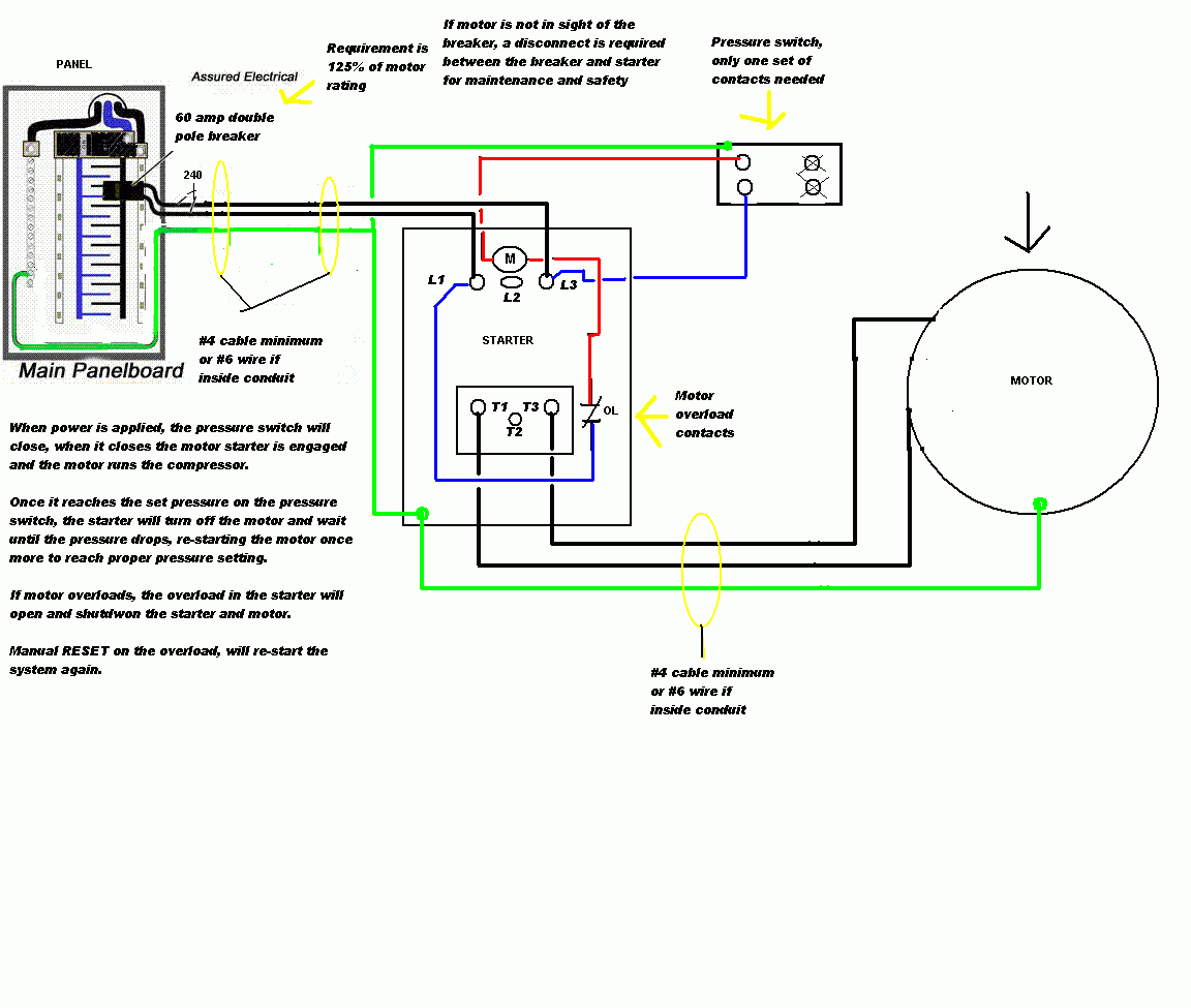
Air compressor wiring requires matching the unit's voltage and amperage demands to your facility or home's electrical grid while adhering to the National Electrical Code (NEC). Proper setup involves determining single-phase versus three-phase power, calculating wire gauge based on distance and load, installing dedicated circuit breakers, and properly connecting pressure switches and magnetic starters to prevent equipment failure and electrical hazards.
Installing or repairing an air compressor involves much more than simply plugging a cord into the nearest wall outlet. Whether you are setting up a small portable unit in a home garage or hardwiring a heavy-duty industrial reciprocating compressor in a commercial workshop, understanding the electrical fundamentals is critical. Electrical mistakes can result in tripped breakers, ruined electric motors, permanent equipment damage, severe shocks, or catastrophic electrical fires.
Because air compressors draw a significant amount of current—especially during startup when the motor overcomes mechanical resistance—they place unique demands on electrical infrastructure. This guide covers the engineering principles, wiring steps, safety mandates, and troubleshooting strategies required to wire an air compressor safely and effectively.
Understanding Air Compressor Electrical Requirements
Before touching a wire, a breaker, or a terminal block, you must examine the motor data plate (nameplate) on your air compressor. The nameplate is your absolute source of truth regarding the electrical specifications of the machine. Never guess or assume the voltage and amperage requirements based on the size of the tank or horsepower ratings alone, as motor efficiencies and designs vary widely.
Voltage and Phase Options
Air compressors generally fall into two primary electrical categories:
- Single-Phase (120V or 230V): Most common in residential garages and small light-duty shops. Smaller units (typically 1.5 horsepower or less) run on standard 120V household circuits. Larger portable and stationary units rated from 2 to 5 horsepower require 230V (often referred to generically as 220V or 240V) single-phase power.
- Three-Phase (208V, 230V, or 460V): Found almost exclusively in industrial, manufacturing, and commercial settings. Three-phase motors are more efficient, run cooler, last longer, and handle heavy startup loads much better than single-phase motors of equivalent horsepower.
Amperage and Motor Starting Loads
Air compressors do not draw a flat, consistent amount of current. When the motor first kicks on to build pressure, it experiences a locked-rotor amperage (LRA) or startup surge that can be three to six times higher than its full-load amperage (FLA) rating listed on the nameplate.
Your circuit protection and wire sizing must account for this startup surge. If the wiring is too thin or the breaker is improperly sized, the voltage will drop significantly during startup, causing the motor to overheat, trip thermal overloads, or burn out prematurely.
Essential Electrical Components for Air Compressor Installations
Hardwiring a stationary air compressor requires several distinct electrical components working in sequence. Skipping any of these components violates electrical safety codes and compromises the longevity of your equipment.
1. Dedicated Circuit and Overcurrent Protection
An air compressor should almost always be installed on a dedicated circuit—meaning no other lights, outlets, or appliances share that breaker. The circuit breaker protects the building wiring from overcurrent conditions and shorts. The breaker size must match the manufacturer's recommendations, which typically scale with the motor's FLA and startup characteristics.
2. Disconnect Switch
For hardwired compressors, safety codes generally require a lockable disconnect switch (safety switch) mounted within sight of the compressor and within easy reach of the operator. This allows maintenance personnel or technicians to physically break the circuit locally before servicing the pressure switch, unloader valve, or motor wiring, preventing accidental startup.
3. Pressure Switch
The pressure switch acts as the brain of the compressor's automatic operation cycle. It contains an internal diaphragm and spring mechanism calibrated to cut power to the motor when the tank reaches its maximum cut-out pressure and restart the motor when pressure drops to the cut-in threshold.
- Direct Control Pressure Switches: Used on smaller 120V and 230V single-phase compressors where the switch contacts are rated to handle the full electrical load of the motor directly.
- Magnetic Starter Controlled Switches: Used on larger motors (typically above 3 to 5 horsepower or any three-phase setup). In this configuration, the pressure switch handles only a low-voltage or low-current control circuit that triggers a heavy-duty magnetic contactor.
4. Magnetic Starter and Overload Relays
A magnetic starter consists of an electromagnetic contactor and thermal overload relays. When signaled by the pressure switch, the electromagnet pulls the contacts closed, sending high-voltage power to the motor. The thermal overload relays monitor the current flowing to the motor; if the motor draws excessive current for too long due to low voltage, mechanical binding, or rapid cycling, the overloads trip and cut power to protect the motor windings.
Wire Sizing and Voltage Drop Calculations
Choosing the correct wire gauge (American Wire Gauge, or AWG) is one of the most critical steps in air compressor wiring. Using wire that is too thin creates electrical resistance, leading to voltage drop, heat generation, and motor failure.
Factors Influencing Wire Selection
- Full-Load Amperage (FLA): The continuous current draw of the motor.
- Distance from Panel: Electricity loses energy as it travels through a conductor. The longer the run from your main electrical breaker panel to the compressor, the thicker (lower AWG number) the wire must be.
- Conductor Material: Copper is standard and handles more current per cross-sectional area than aluminum. If aluminum wiring is used, it must be sized significantly larger and installed with approved anti-oxidation paste and terminal connectors.
- Conduit and Ambient Temperature: Wires bundled tightly in conduit or routed through hot attics or mechanical rooms have lower ampacity ratings and may require derating.
| Motor Horsepower | Voltage (Phase) | Full-Load Amps (Approx.) | Minimum Copper Wire Gauge (Up to 50 ft) | Recommended Breaker Size |
|---|---|---|---|---|
| 1.5 HP | 120V (1-Phase) | 15A – 16A | 12 AWG | 20A |
| 2.0 HP | 230V (1-Phase) | 12A – 14A | 14 AWG or 12 AWG | 20A |
| 3.0 HP | 230V (1-Phase) | 15A – 18A | 10 AWG | 30A |
| 5.0 HP | 230V (1-Phase) | 22A – 28A | 8 AWG | 40A – 50A |
| 5.0 HP | 230V/460V (3-Phase) | 14A / 7A | 10 AWG (for 230V) | 20A – 25A |
Note: The table above provides general reference guidelines. Always consult the specific motor nameplate and local electrical codes before purchasing materials.
Step-by-Step Guide to Hardwiring a Stationary Air Compressor
Hardwiring a compressor requires strict adherence to safety protocols. If you are not a licensed electrician or fully confident in your local electrical codes, hire a qualified professional. Improper electrical installations present lethal shock hazards and insurance liability risks.
Step 1: Shut Off Main Power and Verify
Go to your main electrical service panel, switch off the breaker dedicated to the compressor circuit, and lock/tag out the breaker if applicable. Use a reliable, calibrated multimeter to test the wires at the connection point to ensure zero voltage is present before touching any components.
Step 2: Mount and Route Conduit
Run protective electrical conduit (such as liquid-tight flexible metallic conduit or rigid PVC/EMT depending on local code and indoor/outdoor placement) from your local disconnect switch to the compressor's motor/pressure switch junction box. Secure the conduit firmly to walls or studs to prevent vibration fatigue.
Step 3: Pull Conductors
Pull the appropriate gauge THHN copper wires (typically two hot wires, one neutral if 120V control is needed, and one dedicated ground wire for 230V systems; or three hot wires and a ground for three-phase systems) through the conduit. Leave adequate slack (pigtails) at both ends to make neat, stress-free terminations.
Step 4: Connect Grounding
Safety grounding is non-negotiable. Connect the bare or green ground wire securely to the green grounding screw inside the compressor's terminal enclosure and ensure the metallic chassis of the compressor is bonded back to the earth ground of the main electrical panel.
Step 5: Connect Power Terminals
- Single-Phase 230V: Connect the two hot wires to the input terminals of the pressure switch or magnetic starter. Line color coding typically utilizes black and red for hot wires, though local regulations govern specific color requirements.
- Three-Phase: Connect the three hot lines to the magnetic starter. Crucial Note: For three-phase motors, motor rotation direction matters. After wiring, bump the motor briefly to check rotation. If the motor spins backward (often indicated by an arrow on the pump flywheel or fan housing), swap any two of the three incoming hot lines at the starter to reverse rotation.
Step 6: Final Inspection and Testing
Check all screw terminal connections to ensure they are torqued securely to manufacturer specifications loose connections cause arcing and heat. Close all electrical enclosures, clear the area of tools, restore power at the main panel, and switch on the compressor. Monitor the unit through its first complete pressure cycle to verify correct pressure switch cut-out and smooth motor operation.
Common Air Compressor Wiring Mistakes to Avoid
Avoiding typical wiring pitfalls ensures safety and extends the operational lifespan of your pneumatic equipment.
- Undersized Wiring: Running long distances with thin wire causes severe voltage drops during motor startup. This starves the motor of current, leading to excessive heat generation, tripped thermal overloads, and burned-out windings.
- Sharing Circuits: Running an air compressor on a circuit shared with shop lights, table saws, or battery chargers creates voltage sags and constant nuisance tripping.
- Bypassing Overload Protection: Never wire a compressor motor directly to a wall switch or plug without proper thermal overload protection or fuses matched to the motor's FLA.
- Neglecting Vibration Isolation: Compressors vibrate heavily during operation. Rigid connections without flexible conduit or vibration-damping mounts can crack terminal blocks, break wire strands, and loosen screw connections over time.
Frequently Asked Questions
Can I plug a 230V air compressor into a standard dryer outlet?
While both supply 230V, standard household dryer outlets (typically NEMA 10-30 or 14-30) are protected by breakers and wire gauges tailored for appliance loads, and dryer receptacles use neutral wires improperly configured for motor loads. Furthermore, industrial or heavy-duty shop compressors demand dedicated hardwired lines or industrial-grade locking plugs (such as NEMA L6-30) installed by an electrician to handle high startup surges safely.
Why does my air compressor trip the breaker only when the tank is nearly full?
When the tank is nearly full, the air pressure creates massive back-pressure against the compressor pump pistons. This increases the mechanical load on the electric motor during startup or restart cycles, causing a massive current spike that trips an undersized or weak circuit breaker. Check for unloader valve malfunctions, low line voltage, or a failing check valve that leaves head pressure trapped against the piston.
Do I need a magnetic starter for my single-phase air compressor?
It depends on horsepower and pressure switch ratings. Most smaller single-phase compressors (under 2 or 3 horsepower) use standard direct-action pressure switches capable of handling the load. However, units rated at 5 horsepower or higher draw too much current for standard pressure switch contacts; running them without a magnetic starter will weld the switch contacts shut within a short period.
What is the difference between single-phase and three-phase wiring for compressors?
Single-phase wiring utilizes two hot legs (plus a ground) to deliver 230V power via a sinusoidal wave that alternates direction, requiring a capacitor assist to start the motor. Three-phase wiring utilizes three separate alternating current waves offset by 120 degrees, delivering smooth, balanced power continuously without requiring startup capacitors or centrifugal switches.
How do I troubleshoot a compressor motor that hums but refuses to turn over?
A humming motor that does not start usually indicates a low voltage condition, a stuck pump mechanism, a failed centrifugal switch, or a bad start capacitor. Shut off power immediately to prevent motor burnout, check for physical binding of the pump flywheel by turning it by hand, and verify that your incoming line voltage matches nameplate specs under load.
Conclusion and Next Actions
Wiring an air compressor correctly safeguards your investment, protects your workspace from electrical hazards, and ensures reliable pneumatic performance. Begin by thoroughly reviewing your compressor motor nameplate to identify exact voltage, amperage, and phase specifications. Consult local electrical codes before purchasing materials, and partner with a licensed electrician if you encounter complex multi-phase setups, long wire runs, or panel upgrades. Take time to verify all ground bonds, torque specifications, and breaker pairings before initiating your first pressure test.