Wiring a 4 ohm speaker to a 2 ohm output requires understanding that a single 4 ohm single voice coil speaker cannot safely or effectively be wired down to a 2 ohm load without altering your system design. Amplifiers require careful impedance matching; while you can safely connect a higher impedance speaker (like a 4 ohm) to a lower impedance amplifier output (like 2 ohms), trying to force a lower impedance load onto a higher impedance amplifier risks thermal overload, distortion, and hardware damage. This comprehensive guide details the technical realities, prerequisites, and operational steps required to manage audio impedance mismatches safely in your sound system.
Understanding Audio Impedance and Speaker Loads
Before touching any wiring or audio equipment, it is essential to understand what impedance means in the context of amplifiers and loudspeakers. Impedance, measured in ohms ($\Omega$), is the total opposition that a circuit presents to alternating current (AC) when voltage is applied. In audio engineering, this represents the resistance your speaker voice coil offers to the electrical signal coming from your amplifier.
Amplifiers are engineered to deliver optimal power output at specific load ratings, commonly 4 ohms, 2 ohms, or 1 ohm for car audio subwoofers, and 8 ohms or 4 ohms for home audio systems. When an amplifier specifies that it is stable at a 2 ohm output, it means the internal circuitry can handle the high current draw associated with a 2 ohm load without overheating or triggering protection modes.
However, impedance is not a fixed, static number; it fluctuates dynamically based on the frequency of the audio signal and the physical movement of the speaker cone. This dynamic fluctuation is known as impedance rise. Recognizing how these electrical properties interact prevents costly mistakes when designing or modifying an audio setup.
The Reality of Wiring a Single 4 Ohm Speaker to a 2 Ohm Output
A common point of confusion among audio enthusiasts is whether they can "wire" a single speaker to change its nominal impedance. The definitive technical answer is no. You cannot change the intrinsic impedance of a single voice coil speaker through external wiring configurations alone.
An impedance configuration requires multiple resistive paths to alter the total load seen by the amplifier. Specifically:
- Single Voice Coil (SVC) 4 Ohm Speaker: Has only one positive and one negative terminal. Its impedance is fixed at 4 ohms.
- Dual Voice Coil (DVC) 4 Ohm Speaker: Has two separate 4 ohm voice coils. By wiring these coils in parallel, you can present a combined 2 ohm load to the amplifier. By wiring them in series, you present an 8 ohm load.
If you have a standard single voice coil 4 ohm speaker and connect it to a 2 ohm stable amplifier output, the amplifier will simply see a 4 ohm load. This is a safe operational state, but you will not extract the maximum rated wattage that the amplifier is capable of producing at 2 ohms.
Below is a breakdown of how different speaker configurations interact with amplifier output capabilities:
| Speaker Type & Configuration | Nominal Impedance | Amplifier Output Rating | System Safety & Performance Result |
|---|---|---|---|
| Single Voice Coil (SVC) 4 Ohm | $4,\Omega$ | $2,\Omega$ Stable | Safe operation; amplifier delivers less than maximum power. |
| Dual Voice Coil (SVC) 4 Ohm (Parallel) | $2,\Omega$ | $2,\Omega$ Stable | Ideal match; amplifier delivers full rated power safely. |
| Dual Voice Coil (SVC) 4 Ohm (Series) | $8,\Omega$ | $2,\Omega$ Stable | Extremely safe; lower output volume and reduced power delivery. |
| Two Single Voice Coil 4 Ohm Speakers (Parallel) | $2,\Omega$ | $2,\Omega$ Stable | Ideal match; splits power evenly across both speakers at a 2 ohm load. |
Prerequisites and Tools for Speaker Wiring
Executing any audio wiring project requires proper preparation and safety gear to protect both the user and the sensitive electronic components. Working with power amplifiers, even in low-voltage 12-volt car audio environments, carries risks of short circuits, blown fuses, and permanent hardware failure.
Required Tools and Materials
- Digital Multimeter (DMM): Essential for verifying actual electrical resistance and checking for continuity or accidental grounding.
- Wire Strippers: For cleanly removing insulation from speaker wire without nicking the copper strands.
- Speaker Wire: Heavy-gauge copper wire (typically 12 to 16 AWG) capable of handling the current flow without excessive resistance.
- Connectors and Terminals: Crimp connectors, spade connectors, or heat-shrink tubing to secure physical connections and prevent fraying.
- Basic Hand Tools: Screwdrivers and a socket set for securing speaker terminals and mounting hardware.
Safety Precautions
- Disconnect Power: Always disconnect the negative battery terminal in automotive installations or unplug home audio receivers from the wall outlet before modifying wiring.
- Verify Amplifier Specifications: Check the manufacturer manual to confirm the absolute minimum stable impedance rating of your amplifier channels. Never drop a load below the manufacturer's specified minimum.
- Inspect Wiring Integrity: Ensure there are no exposed wire strands touching adjacent terminals, which causes dangerous short circuits.
Step 1: Evaluate Your Speaker and Amplifier Specifications
The first active step in any wiring project is a rigorous audit of your hardware specifications. Do not rely on guesswork or general assumptions about what your gear can handle.
Locate the exact model numbers of both your speaker and your amplifier. Consult the user manuals or manufacturer specification sheets to identify:
- The Speaker's Voice Coil Configuration: Determine if the speaker is a Single Voice Coil (SVC) or Dual Voice Coil (DVC) unit. Measure the DC resistance across the speaker terminals using a digital multimeter set to the lowest ohm setting. Note that the measured DC resistance (often reading around 3.2 to 3.8 ohms for a 4 ohm speaker) will be slightly lower than the nominal AC impedance rating, which is normal.
- The Amplifier's Output Channels and Ratings: Verify whether your amplifier is a mono block or multi-channel unit, and check its continuous power output (RMS) ratings at 4 ohms and 2 ohms.
If your speaker is a dual voice coil 4 ohm model, you have the physical capability to wire it to a 2 ohm load. If your speaker is a single voice coil 4 ohm model, you must either accept operating at a 4 ohm load or add a second compatible speaker to achieve a 2 ohm load through parallel wiring.
Step 2: Determine the Correct Wiring Topology (Series vs. Parallel)
Once you have identified your hardware capabilities, you must choose the appropriate wiring topology. Because impedance changes based on how loads are combined in a circuit, mathematics dictates your configuration options.
Parallel Wiring Formula
When wiring two identical loads (such as two 4 ohm speakers or two 4 ohm voice coils) in parallel, the total impedance is halved: $$\text{Total Impedance} = \frac{\text{Impedance of One Load}}{\text{Number of Loads}} = \frac{4,\Omega}{2} = 2,\Omega$$
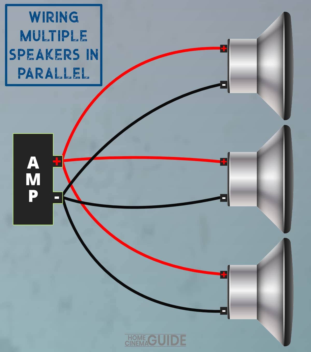
To wire in parallel, you connect all positive terminals together and all negative terminals together. This is the exact method required to present a 2 ohm load to your amplifier output using compatible components.
Series Wiring Formula
When wiring loads in series, the individual impedances are added together: $$\text{Total Impedance} = \text{Load 1} + \text{Load 2} = 4,\Omega + 4,\Omega = 8,\Omega$$
Series wiring increases total resistance, which reduces current draw and decreases the power output delivered by the amplifier. This is counterproductive if your goal is to utilize a 2 ohm output level. Therefore, parallel wiring is the mandatory choice for achieving a 2 ohm load.
Step 3: Prepare and Strip the Speaker Wire
With your topology selected, prepare the physical wiring connections. Clean, precise connections ensure optimal signal transfer and prevent mechanical failures due to vibration or corrosion.
- Measure the required distance between your amplifier output terminals and your speaker terminals, adding a small amount of slack to prevent tension on the connections.
- Use professional wire strippers to remove approximately 3/8 inch to 1/2 inch of insulation from the ends of the speaker wire, exposing clean, bright copper strands.
- Inspect the exposed copper strands. If the wire is old and oxidized (appearing dull or blackish), trim the oxidized section back until fresh copper is visible.
- Twist the fine copper strands tightly together in a single direction to eliminate stray strands that could cause a short circuit across amplifier terminals. If using bare wire connections, consider tinning the tips lightly with a soldering iron to hold the strands together.
Step 4: Execute the Wiring Connections
The physical connection phase requires meticulous attention to polarity. Maintaining correct positive ($+$) and negative ($-$) phase alignment ensures that multiple speakers or voice coils move in unison, maximizing acoustic efficiency and bass response.
- If using a Dual Voice Coil (DVC) 4 Ohm Speaker (Parallel Wiring for 2 Ohms):
- Run a jumper wire from positive terminal 1 to positive terminal 2.
- Run a jumper wire from negative terminal 1 to negative terminal 2.
- Connect the primary positive wire from the amplifier's positive output terminal to positive terminal 1 on the speaker.
- Connect the primary negative wire from the amplifier's negative output terminal to negative terminal 1 on the speaker.
- If using Two Single Voice Coil (SVC) 4 Ohm Speakers (Parallel Wiring for 2 Ohms):
- Connect a wire from the amplifier's positive output terminal to the positive terminal of Speaker A.
- Run a jumper wire from the positive terminal of Speaker A to the positive terminal of Speaker B.
- Connect a wire from the amplifier's negative output terminal to the negative terminal of Speaker A.
- Run a jumper wire from the negative terminal of Speaker A to the negative terminal of Speaker B.
- Ensure all terminal screws or spring clips clamp down firmly on the bare wire, not on the plastic insulation. Apply heat-shrink tubing or electrical tape over any exposed terminal connections to protect against accidental grounding.
Step 5: Verify Impedance and Test the System
Never power up an audio system immediately after finishing wiring without conducting diagnostic checks. Verification protects your investment from catastrophic amplifier failure.
- Multimeter Resistance Check: With the amplifier completely powered off and disconnected from power sources, place your digital multimeter probes across the final speaker wires that connect to the amplifier. For a true 2 ohm parallel configuration, your meter should read approximately 1.6 to 2.2 ohms of DC resistance. If the meter reads open-circuit (infinite resistance) or zero ohms (a dead short), do not turn on the amplifier; recheck your wiring immediately.
- Low-Volume Functional Test: Reconnect power to your amplifier, set the gain structure and source unit volume to a very low level, and play a familiar audio track with moderate dynamic range.
- Listen for Distortion: Slowly increase the volume while listening closely for clipping, rattling, or amplifier protection mode triggers. Monitor the amplifier chassis temperature during the first ten minutes of operation to ensure it remains within normal operating limits.
Common Mistakes to Avoid
Audio wiring mistakes can lead to damaged hardware, blown fuses, or poor acoustic performance. Avoid these frequent errors:
- Forcing a Single SVC 4 Ohm Speaker to 2 Ohms: Assuming that amplifier settings or twisted wires can magically drop a single 4 ohm voice coil down to 2 ohms. As established, impedance is a fixed physical property of the voice coil.
- Ignoring Phase Alignment: Mixing up positive and negative polarities results in out-of-phase sound, characterized by weak bass cancellation and poor stereo imaging.
- Using Insufficient Wire Gauge: Using thin, low-gauge wire (such as 18 or 20 AWG) over long distances introduces unnecessary electrical resistance, reducing power transfer and generating excess heat.
- Exceeding Amplifier Limits: Connecting loads lower than the manufacturer's rated minimum stability threshold, which forces the amplifier protection circuit to engage or causes thermal shutdown.
Frequently Asked Questions
Can I damage my amplifier by connecting a 4 ohm speaker to a 2 ohm output?
No, connecting a higher impedance speaker (4 ohms) to an amplifier output designed for lower impedance (2 ohms) is electrically safe. The amplifier will simply produce less power than its maximum rated output at 2 ohms because the higher resistance restricts current flow. The reverse scenario—connecting a 2 ohm speaker to a 4 ohm amplifier—is dangerous and can cause overheating.
What happens if I wire two 4 ohm speakers in parallel?
Wiring two 4 ohm speakers in parallel combines their electrical paths, cutting the total impedance in half to a 2 ohm load. This allows a 2 ohm stable amplifier to deliver its maximum rated power output evenly across both speakers.
Why does my multimeter read slightly under 2 ohms for a 2 ohm load?
A digital multimeter measures DC resistance, whereas speaker impedance is an AC measurement that varies with frequency. It is completely normal for a multimeter to read slightly lower (e.g., 1.6 to 1.8 ohms) than the nominal 2 ohm rating due to the inherent properties of copper voice coils.
Can I bridge a 2-channel amplifier into a 4 ohm speaker to get a 2 ohm output?
Bridging combines two amplifier channels to drive a single load, which effectively doubles the voltage swing and increases power output. However, bridging typically requires a higher minimum impedance load (often 4 ohms minimum for bridged mode) rather than lowering it to 2 ohms. Always consult your specific amplifier manual before attempting bridged configurations.
Final Recommendations
Successfully managing audio impedance matching comes down to respecting the electrical parameters specified by your hardware manufacturers. If you are working with a single voice coil 4 ohm speaker, recognize its limitations and do not attempt impossible wiring tricks; instead, pair it with a compatible 4 ohm amplifier output, or expand your system with a second identical speaker to safely achieve a true 2 ohm parallel load. Always double-check your connections with a digital multimeter before powering up your system to ensure safe, reliable, and high-fidelity audio performance.