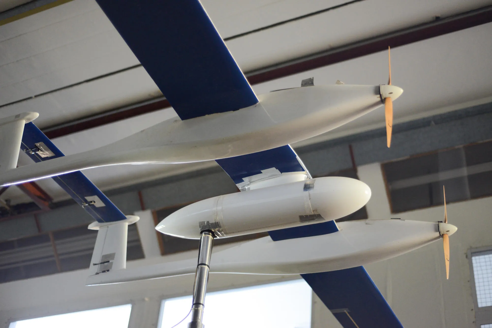
Aeronautical design is the multidisciplinary engineering discipline dedicated to conceptualizing, analyzing, and building aircraft by balancing aerodynamics, propulsion, structural mechanics, and flight avionics. The field faces unprecedented emerging challenges driven by strict environmental net-zero mandates, high-speed flight physics, novel composite manufacturing processes, autonomous flight control integration, and the complex certification of non-traditional airframe architectures.
Foundations of Aeronautical Design and Systems Integration
Aeronautical design relies on balancing physics, material limits, and operational requirements. Traditionally, aircraft development moves through three sequential phases: conceptual design, preliminary design, and detailed design.
During the conceptual design phase, engineers define the aircraft’s overarching geometry, payload capacity, operational range, and target flight regime (subsonic, transonic, supersonic, or hypersonic). Key sizing metrics—such as the Maximum Take-Off Weight (MTOW), wing loading ($W/S$), and thrust-to-weight ratio ($T/W$)—are established using empirical historical data and fundamental aerodynamic equations.
The preliminary design phase refines these baseline parameters through advanced computational methods. High-fidelity Computational Fluid Dynamics (CFD) simulates airflow across complex aerodynamic surfaces, evaluating skin friction drag, pressure distribution, and boundary layer stability. Concurrently, Finite Element Analysis (FEA) estimates structural load paths, stress concentrations, and deflection under peak aerodynamic loads.
- Conceptual Phase
- Sizing Parameters
- Target Range & MTOW
- Baseline Geometry
- Preliminary Phase
- High-Fidelity CFD
- FEA Structural Stress
- Flight Dynamics Modeling
- Detailed Phase
- Component CAD Drafts
- Manufacturing Tolerances
- Production Tooling Specs
In the detailed design phase, abstract aerodynamic surfaces and structural skeletons transform into manufacturable Computer-Aided Design (CAD) models. Every bracket, fastener, wiring harness, and hydraulic line is defined alongside tight manufacturing tolerances.
Modern aeronautical design has evolved from this linear pipeline into Multidisciplinary Design Optimization (MDO) and Model-Based Systems Engineering (MBSE). Rather than analyzing aerodynamics, structures, and propulsion in isolation, MDO couples these domains within unified computational frameworks. This approach allows engineers to identify design trade-offs early—such as sacrificing minor aerodynamic efficiency to gain significant structural weight savings or improving engine thermal integration.
Key Emerging Challenges in Aeronautical Design
As global aviation targets net-zero carbon emissions by 2050 and explores novel operational concepts—such as Urban Air Mobility (UAM) and commercial supersonic transport—aeronautical engineers face complex physical, operational, and regulatory constraints.
- Emerging Challenges in Aeronautical Design
- Decarbonization & Alternative Propulsion
- High-Speed Aerodynamics & Gas Dynamics
- Advanced Composites & Manufacturing
- Autonomous & Certifiable AI Systems
- Aeroacoustics & Environmental Noise Limits
1. Decarbonization and Alternative Propulsion Integration
Transitioning away from conventional Jet A aviation fuel presents significant challenges for aircraft sizing, configuration, and weight management.
Sustainable Aviation Fuels (SAF)
Drop-in SAFs derived from synthetic Fischer-Tropsch processes or hydroprocessed esters and fatty acids (HEFA) offer immediate carbon-reduction benefits without requiring major structural airframe redesigns. However, SAFs often lack the aromatic hydrocarbon content present in conventional jet fuel, which historically aided fuel system seal swelling. Engineers must redesign fuel delivery materials, elastomeric seals, and combustor fuel nozzles to handle 100% unblended SAF operations without degrading engine efficiency or seal integrity.
Liquid Hydrogen ($LH_2$) Systems
Liquid hydrogen offers a gravimetric energy density of roughly 120 MJ/kg—nearly three times that of standard jet fuel (~43 MJ/kg). However, its volumetric energy density is roughly four times lower, requiring much larger fuel volumes.
Hydrogen must be stored as a cryogenic liquid at temperatures below 20 Kelvin (-253°C) under high pressure. This requirement makes conventional flexible wing fuel tanks unusable, forcing designers to incorporate large, cylindrical, thermally insulated pressure vessels inside the main fuselage.
- Conventional Jet A Configuration:
- Cockpit, Passengers, Tail
- Fuel stored inside wings
- Liquid Hydrogen (LH2) Configuration:
- Cockpit, LH2 Tank, Passengers, Tail
- Large fuselage cryogenic tank
Placing bulky cryogenic tanks within the fuselage shifts the aircraft's center of gravity (CG), increases total fuselage wetted area, elevates skin friction drag, and reduces available cabin space. Designers are re-evaluating unconventional configurations—such as Blended Wing Body (BWB) concepts—to accommodate large volume requirements without incurring extreme aerodynamic drag penalties.
Hybrid-Electric and All-Electric Architectures
Electric propulsion replaces central gas turbine engines with distributed electric fans driven by high-power motors. While distributed electric propulsion (DEP) improves aerodynamic efficiency via wing-blown lift, current battery energy storage technologies remain a major bottleneck.
Lithium-ion battery packs achieve gravimetric energy densities of 250 to 300 Wh/kg, far below Jet A's effective energy density of over 12,000 Wh/kg. Consequently, fully electric systems are restricted to light trainer aircraft and short-range urban air mobility vehicles.
Hybrid-electric designs balance these trade-offs by pairing compact gas-turbine generators with electric motor-driven propulsors. However, managing high-voltage electrical distribution (exceeding 1 kV) at high altitudes introduces severe challenges, including thermal dissipation in low-density air and dielectric breakdown risks caused by partial electrical discharge (corona effect).
2. Advanced Aerodynamics and High-Speed Flight Dynamics
Navigating high-speed regimes introduces complex aerodynamic and thermodynamic phenomena.
Natural Laminar Flow (NLF) and Boundary Layer Control
At subsonic and transonic cruise conditions, boundary layer transition from smooth laminar flow to turbulent flow significantly increases skin friction drag. Designing wings for Natural Laminar Flow (NLF) requires precise pressure gradient tailoring across the airfoil surface to delay boundary layer turbulence without active suction systems.
Achieving this performance demands micro-inch surface smoothness. Even minor bugs, ice accretion, or manufacturing surface step-discontinuities can trigger premature turbulent transition, negating the aerodynamic efficiency gains.
- Laminar Boundary Layer (Low Drag)
- Wing Surface
- Smooth, parallel fluid layers
- Turbulent Boundary Layer (High Drag)
- Wing Surface
- Eddies, cross-mixing, pressure drops
Boundary Layer Ingestion (BLI)
Boundary Layer Ingestion integrates engines directly into the aft fuselage skin to ingest slow-moving boundary layer air along the airframe body. Ingesting this slower air reduces wake kinetic energy losses and improves overall propulsive efficiency.
However, BLI forces engine fan blades to operate in highly distorted, non-uniform airflow fields. This non-uniformity induces cyclic aerodynamic loading across the rotor blades, escalating structural fatigue, blade vibration, and acoustic noise generation.
Supersonic and Hypersonic Aerothermodynamic Coupling
Designing commercial supersonic aircraft (Mach 1.4 to 2.2) and military hypersonic vehicles (Mach 5+) requires managing intense shockwave interactions and thermal loads. Supersonic design focuses on reducing wave drag and controlling sonic boom signatures at ground level.
Engineers use shaped-sonic-boom techniques to spread shockwaves across the airframe length, softening the ground pressure rise ($\Delta P$). At hypersonic speeds, aerothermal heating dominates airframe design.
Shockwave-Boundary Layer Interactions (SWBLI) generate extreme localized heat fluxes and intense dynamic pressure oscillations. This environment requires integrated thermal protection systems (TPS), actively cooled structural panels, and complex ceramic matrix composite (CMC) skin structures capable of enduring temperatures over 1,600°C.
3. Next-Generation Composite Materials and Structural Integrity
Modern airframes rely heavily on carbon-fiber-reinforced polymers (CFRP) to reduce structural weight. However, advanced requirements are driving a shift toward newer material architectures.
| Traditional Thermosets (Epoxy) | Advanced Thermoplastics (PEEK / PEKK) |
|---|---|
| Irreversible chemical cross-linking | Re-meltable, thermoformable polymer chains |
| Extended autoclave cure cycles (hours) | Fast stamp-forming processing (minutes) |
| Susceptible to impact micro-cracks | Higher fracture toughness & moisture resistance |
| Difficult to recycle at end-of-life | Fully recyclable via thermal reprocessing |
Thermoplastic Composites vs. Thermosets
Traditional aerospace composites rely on thermosetting epoxy resins, which require lengthy high-pressure curing cycles inside large industrial autoclaves. Modern programs are transitioning to high-performance thermoplastic matrices, such as Polyetheretherketone (PEEK) and Polyetherketoneketone (PEKK).
Thermoplastics offer superior fracture toughness, lower moisture absorption, and thermal formability, allowing parts to be stamp-formed and welded in minutes rather than cured over hours. This processing shift eliminates complex mechanical fasteners, reducing structural mass and assembly time.
Additive Manufacturing and Topology Optimization
Metal Additive Manufacturing (AM)—such as Laser Powder Bed Fusion (LPBF) using Ti-6Al-4V titanium alloys or Inconel 718 nickel superalloys—enables complex structural components designed through algorithmic topology optimization. Engineers can create biomimetic, hollow, or lattice-filled load-bearing brackets that retain structural strength while eliminating unneeded internal material.
The primary challenge in additive manufacturing lies in structural certification. Microstructural voids, un-fused powder inclusions, residual thermal stress, and anisotropic grain growth require rigorous non-destructive evaluation (NDE) techniques, including micro-focus X-ray Computed Tomography ($\mu CT$), to verify structural integrity before flight deployment.
4. Artificial Intelligence, Autonomy, and Flight Controls
Integrating advanced autonomous control systems and machine learning into safety-critical flight electronics changes long-standing software verification methods.
Flight-Critical Autonomous Systems
Uncrewed Aircraft Systems (UAS) and Urban Air Mobility (UAM) platforms depend on autonomous flight control systems to manage dynamic environments, avoid obstacles, and navigate in GNSS-denied environments. These systems process multi-sensor inputs—combining Optical Camera, LiDAR, Radar, and Inertial Measurement Unit (IMU) data—to make real-time flight path adjustments.
The Certification Paradox of Non-Deterministic AI
Traditional avionics software standards, such as RTCA DO-178C (Software Considerations in Airborne Systems and Equipment Certification), require deterministic behavior: every specific input must yield a predictable, repeatable output.
Modern Artificial Intelligence (AI) and Machine Learning (ML) models—especially deep neural networks used in vision-based target classification and adaptive control—are non-deterministic and operate like black boxes.
Engineers and aviation safety authorities, such as the Federal Aviation Administration (FAA) and the European Union Aviation Safety Agency (EASA), are building new assurance frameworks. These frameworks focus on runtime assurance monitoring, bounding-box safety nets, and formal mathematical verification to guarantee that neural-network-driven commands cannot exceed safe flight envelope boundaries.
5. Aeroacoustics and Environmental Impact
Community noise standards dictate where and when aircraft can operate, making noise reduction a primary design requirement.
- Aeroacoustic Mitigation Strategies
- Rotor & Propeller Aerodynamics
- Blade Tip Shaping (Anhedral / Scimitar)
- Variable Phase RPM Synchronization
- Lower Tip Speed Mach Numbers ($M_{tip} < 0.65$)
- Airframe Noise Reduction
- Trailing-Edge Serrations
- Continuous Slapless Flap Trailing-Edges
- Porous Landing Gear Fairings & Acoustic Liners
- Rotor & Propeller Aerodynamics
Low-Noise Rotor and Propeller Design
For eVTOL platforms operating in high-density urban environments, acoustic signatures are a major factor in public acceptance. Rotor noise stems from blade-vortex interaction (BVI), where a rotating blade collides with the turbulent tip vortex shed by the preceding blade.
Engineers mitigate BVI by altering rotor blade planforms, incorporating swept blade tips, using uneven blade spacing, and tuning rotational speeds ($M_{tip} < 0.65$). Distributed propulsion systems can also dynamically synchronize rotor phases to alter acoustic frequencies and reduce ground-level noise.
Airframe Noise Reduction
As jet engine high-bypass-ratio turbofans become quieter, airframe noise from deployed landing gear, wing trailing edges, and high-lift devices (slats and flaps) becomes a major source of noise during approach and landing.
Engineers address airframe noise using trailing-edge acoustic serrations, porous mesh airframe treatments, continuous flap transition fairings, and aerodynamically sculpted landing gear doors to minimize turbulent wake formation.
Comparative Analysis of Aircraft Architectures
Understanding the trade-offs between conventional and emerging airframe designs requires comparing energy sources, structural considerations, and operational constraints across different aircraft classes.
| Architecture Type | Primary Energy Source | Gravimetric Energy Density | Relative Structural Complexity | Key Aerodynamic / Engineering Challenge | Primary Certification Hurdle |
|---|---|---|---|---|---|
| Conventional Turbofan (e.g., B787, A350) | Kerosene / Jet A-1 | ~12,000 Wh/kg | Baseline | Managing transonic wave drag and engine fan noise | Well-established (FAR Part 25 / EASA CS-25) |
| Sustainable Fuel (SAF) | Synthetic / Bio-derived Hydrocarbons | ~11,800 Wh/kg | Low | Combustor thermal profiling and seal material compatibility | Chemical drop-in compliance & supply verification |
| Liquid Hydrogen ($LH_2$) Transports | Cryogenic Liquid $H_2$ (20 K) | ~33,300 Wh/kg (Fuel) / Low (Tank System) | High | Large internal tank integration, CG shifts, and thermal insulation | Cryogenic safety, pressure venting, and crashworthiness |
| Hybrid-Electric / eVTOL | Li-ion Batteries + Small Gas Turbine | ~250–400 Wh/kg (Battery) | Very High | Aeroacoustic BVI, high-voltage thermal dissipation | Novel airworthiness (EASA SC-VTOL, FAA Part 21.17b) |
| Commercial Supersonic (e.g., Mach 1.7+) | High-Density Jet Fuel / SAF | ~11,500 Wh/kg | High | Shockwave shaping, wave drag reduction, thermal loads | Sonic boom overpressure limits over land |
Regulatory, Certification, and Supply Chain Obstacles
Developing advanced aeronautical designs extends beyond solving engineering equations; it requires navigating strict regulatory frameworks and managing complex global supply chains.
- Regulatory & Operational Bottlenecks
- Evolving Certification Schemes (EASA SC-VTOL, FAA Special Conditions)
- Raw Material Supply Risks (Aerospace-grade Titanium, Carbon Fiber Prepregs)
- Lifecycle Environmental Assessments (Whole-Life Carbon & Recycling Metrics)
Adapting Airworthiness Standards
Certification authorities ensure that commercial aircraft meet strict safety levels—typically requiring a failure probability of less than one catastrophic event per $10^9$ flight hours ($10^{-9}$). Existing regulatory codes, such as FAA Part 25 or EASA CS-25, were developed for fixed-wing aircraft powered by traditional jet engines.
Non-traditional configurations—such as tilt-rotor eVTOLs or hydrogen-powered aircraft—do not fit neatly into these established categories. Regulators must issue targeted frameworks, such as EASA’s Special Condition for Small-Category VTOL Aircraft (SC-VTOL).
These evolving standards mean airframe manufacturers must prove compliance for novel failure modes—such as battery thermal runaway propagation, multiple rotor failure interactions, and high-voltage arc fault containment—before completing their final designs.
Supply Chain Fragility and Critical Materials
Modern aeronautical designs depend on complex supply chains for specialized materials:
- Aerospace-Grade Titanium (Ti-6Al-4V): Vital for high-stress structural fittings, landing gear assemblies, and high-temperature engine components. Geographical concentration of titanium processing creates supply vulnerabilities for major aircraft manufacturers.
- Pre-impregnated Carbon Fiber (Prepregs): Advanced composite production requires consistent precursor chemicals (Polyacrylonitrile or PAN) and uninterrupted cold-chain logistics to prevent premature resin curing during transit.
- Rare Earth Elements (Neodymium, Dysprosium): Essential for high-torque permanent magnet motors used in electric propulsion architectures, creating exposure to global trade disruptions.
Lifecycle Assessment (LCA) and Recycling
Sustainability goals are expanding beyond in-flight emissions to cover total lifecycle environmental impact. Historical thermoset composite airframes present challenging end-of-life disposal problems, as cross-linked epoxy matrices cannot be easily melted down or recycled, sending retired airframes to land-fills or storage yards.
Regulatory mandates are pushing engineers to adopt recyclable thermoplastic resins, design for automated disassembly, and establish closed-loop recycling processes for carbon fiber reclaim.
Best Practices and Strategic Frameworks for Aerospace Engineers
Addressing these concurrent challenges requires modern software, testing, and system architecture methodologies.
- Recommended Engineering Best Practices
- Adopt Model-Based Systems Engineering (MBSE)
- Unify software, mechanical, and electrical models.
- Integrate Physics-Informed Neural Networks (PINNs)
- Accelerate CFD/FEA iterations from days to minutes.
- Bridge TRL to MRL Early in Development
- Match lab prototypes to industrial tooling.
- Adopt Model-Based Systems Engineering (MBSE)
1. Implement Model-Based Systems Engineering (MBSE)
Replace static, document-based engineering workflows with unified system modeling environments (using SysML or specialized MBSE platforms). MBSE provides a single source of truth connecting system requirements directly to CAD geometry, CFD simulation results, and software code, ensuring that an update to an aerodynamic surface automatically propagates down to structural and flight control analyses.
2. Accelerate Iterations with Physics-Informed Neural Networks (PINNs)
Combine traditional CFD solvers with Physics-Informed Neural Networks (PINNs). By embedding fundamental physical laws (such as the Navier-Stokes equations and conservation of mass) directly into deep learning loss functions, PINNs can predict complex aerodynamic flow fields and pressure distributions in seconds rather than hours. This enables deep aerodynamic shape optimizations early in the conceptual design phase.
3. Align Technology Readiness (TRL) with Manufacturing Readiness (MRL)
A major trap in advanced aeronautical design is developing a aerodynamically optimized component at Technology Readiness Level 4 (lab validation) that cannot be manufactured efficiently at Manufacturing Readiness Level 7+ (production environment). Aerospace design teams should incorporate Manufacturing Readiness Assessments (MRA) alongside concept development, evaluating tooling constraints, cycle times, non-destructive inspection access, and supply chain stability long before finalizing airframe geometry.
Frequently Asked Questions
What is the primary bottleneck in decarbonizing commercial aviation?
The primary bottleneck is the low gravimetric and volumetric energy density of alternative power sources compared to conventional jet fuel. While Jet A contains roughly 12,000 Wh/kg of energy, present-day lithium batteries achieve only 250 to 300 Wh/kg. Liquid hydrogen offers high energy per unit mass but requires four times the storage volume of Jet A and must be kept at cryogenic temperatures (-253°C), requiring heavy, bulky pressure tanks that complicate airframe design.
How does liquid hydrogen storage alter traditional aircraft fuselage design?
Conventional jet fuel is stored inside the hollow internal spaces of an aircraft’s wings. Liquid hydrogen cannot be stored in thin, flexible wing spaces because it requires heavy, insulated, cylindrical cryogenic pressure vessels. Placing these bulky tanks inside the main fuselage shifts the aircraft's center of gravity, consumes large amounts of potential passenger or cargo space, and increases total body surface area, which adds aerodynamic drag.
Why is certifying artificial intelligence in flight-critical systems challenging?
Airworthiness authorities require deterministic software under standards like RTCA DO-178C, meaning a specific input must always produce an identical, mathematically verifiable output. Many AI algorithms—particularly deep neural networks used for visual recognition and adaptive control—operate non-deterministically. Proving that an adaptive neural network will not produce an unsafe control input under unencountered flight conditions requires new verification methods, such as bounded runtime assurance and formal mathematical proofs.
What are the main benefits of thermoplastic composites over thermoset composites?
Thermoplastic composites (such as PEEK and PEKK) can be melted, reshaped, and welded multiple times, whereas thermoset epoxies undergo irreversible chemical cross-linking during curing. Thermoplastics enable rapid stamp-forming manufacturing techniques, eliminate long autoclave cure cycles, offer superior fracture toughness and moisture resistance, and can be melted down and recycled at the end of the aircraft's operational lifespan.
How does Boundary Layer Ingestion (BLI) improve aerodynamic efficiency?
Boundary Layer Ingestion integrates aircraft engines into the aft skin of the fuselage so they draw in the slow-moving air layer created by skin friction along the airframe body. Accelerating this slower air requires less net propulsive energy than ingesting undisturbed free-stream air, improving overall propulsive efficiency. However, the non-uniform airflow entering the engine fan blades increases structural vibration and dynamic dynamic stress, requiring reinforced fan design.
Future Outlook in Aeronautical Engineering
The future of aeronautical design depends on balancing competing design priorities. Achieving carbon-neutral flight, higher transport speeds, and autonomous operation requires engineers to move beyond traditional tube-and-wing configurations.
Success will depend on how effectively the industry combines high-performance computational modeling, advanced material science, low-emission propulsion architectures, and modern airworthiness certification standards into scalable, safe, and commercially viable aircraft.