The 555 timer integrated circuit is a versatile, robust, and inexpensive component capable of generating precise time delays, pulses, and oscillations, making it an essential building block for countless electronics projects ranging from simple flashing LED lights to complex pulse-width modulation motor controllers.
Introduction to the 555 Timer IC
The 555 timer integrated circuit, introduced by Signetics in 1971, remains one of the most successful and widely used semiconductor devices in the history of electronics. Despite decades of technological advancement and the dominance of microcontrollers in modern design, the classic 555 timer retains a dedicated following among hobbyists, students, and professional engineers alike. Its enduring appeal lies in its simplicity, reliability, low cost, and ability to handle both analog timing tasks and digital logic interfacing without requiring complex programming or software development environments.
Understanding how to construct 555 timer circuits projects requires a foundational grasp of the chip's internal architecture and pin configuration. The standard 555 timer typically comes in an 8-pin dual-in-line package (DIP) or a surface-mount variant. Each pin serves a distinct purpose: Ground, Trigger, Output, Reset, Control Voltage, Threshold, Discharge, and Supply Voltage ($V_{CC}$). Inside the package, a voltage divider network establishes reference voltages for two internal comparators, which in turn control an RS flip-flop and a high-current output stage.
Working with this component involves three primary operating modes: astable (free-running oscillator generating continuous pulses), monostable (one-shot pulse generator triggered by an external input), and bistable (acting as a basic flip-flop switch). Selecting the correct mode depends entirely on the requirements of your specific application, whether you are building a simple audio tone generator or an automated industrial timer.
Essential Prerequisites and Hardware Requirements
Before assembling any electronics project involving the 555 timer, you must gather the appropriate components, tools, and safety equipment. While the 555 timer is forgiving and operates across a wide voltage range—typically from $4.5\text{V}$ to $15\text{V}$ for standard bipolar versions (such as the NE555) and down to $2\text{V}$ for CMOS variants (such as the TLC555)—careful attention to component ratings prevents hardware damage and ensures predictable circuit behavior.
Core Components and Tools Needed
- 555 Timer IC: Choose an NE555 for general-purpose applications or a CMOS variant for low-current and battery-powered projects.
- Power Source: A regulated DC power supply, a $9\text{V}$ battery, or a USB-powered breadboard power module.
- Passive Components: A diverse selection of resistors (ranging from $100,\Omega$ to $1,\text{M}\Omega$) and capacitors (ceramic and electrolytic, ranging from $10,\text{nF}$ to $100,\mu\text{F}$).
- Output Devices: Light-emitting diodes (LEDs), piezoelectric buzzers, small DC motors, or electromechanical relays.
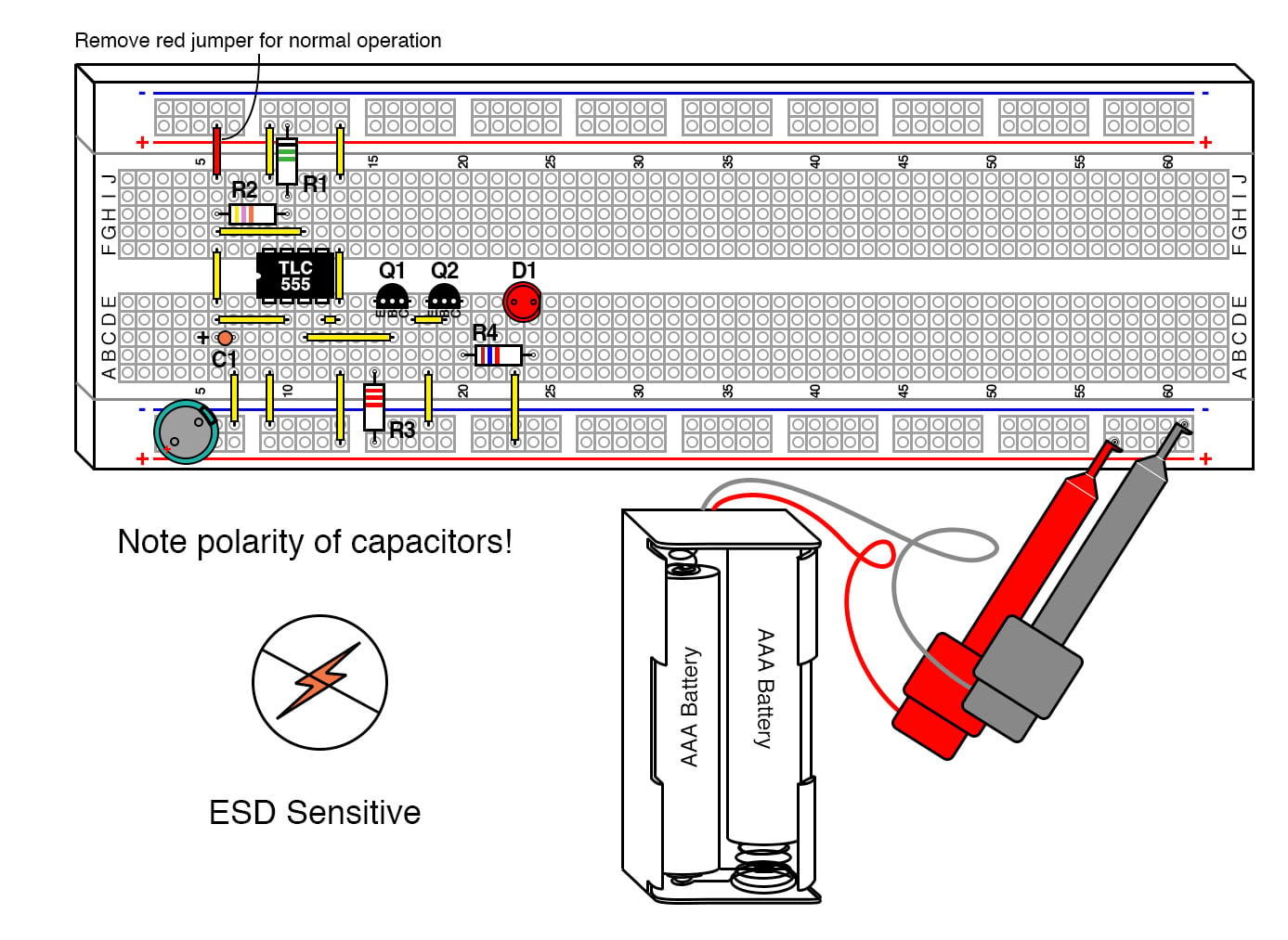
- Prototyping Equipment: A solderless breadboard, jumper wires, a digital multimeter for voltage and continuity testing, and optionally an oscilloscope for observing waveform transitions.
Safety considerations are minimal given the low voltages involved, but standard electronics safety practices still apply. Always disconnect power before modifying circuit connections on your breadboard. Pay close attention to the polarity of electrolytic capacitors and LEDs; reversing them can cause component failure or rupture. Furthermore, ensure that inductive loads—such as small motors or relays—are paired with a flyback diode (such as a 1N4001) across their terminals to protect the 555 timer's output stage from voltage spikes induced by collapsing magnetic fields.
Core Operating Modes of the 555 Timer
To successfully build varied projects, you must master the three fundamental wiring configurations of the IC. Each mode leverages specific pin connections to manipulate the internal comparators and flip-flop.
1. Astable Mode (Continuous Oscillator)
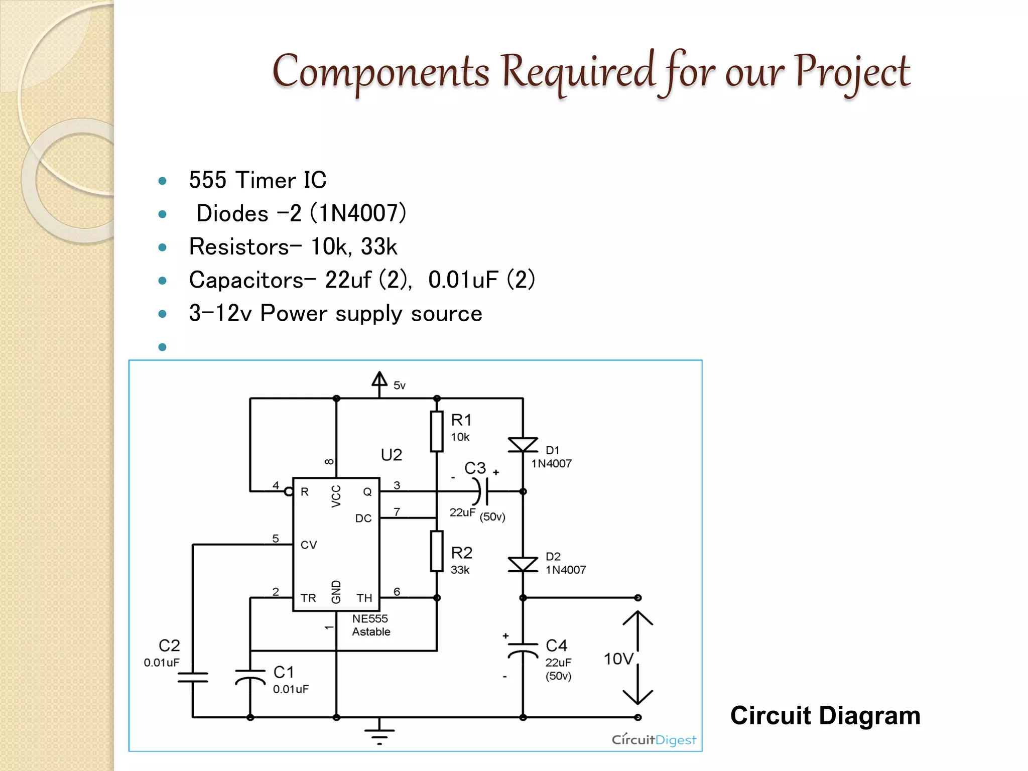
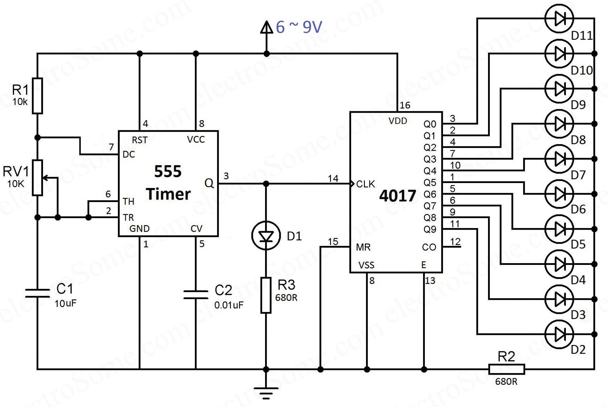
In astable mode, the circuit has no stable states; it continuously switches between high and low logic levels, generating a continuous square wave. This configuration is ideal for flashing lights, clock generators, and tone synthesizers. The frequency of oscillation and the duty cycle are determined by the values of two external resistors ($R_1$ and $R_2$) and one capacitor ($C$).
The capacitor charges through $R_1$ and $R_2$ until its voltage reaches two-thirds of $V_{CC}$, triggering the upper comparator, which forces the discharge pin low and causes the capacitor to discharge through $R_2$ until its voltage drops to one-third of $V_{CC}$. This cycle repeats indefinitely. The frequency ($f$) can be calculated using the standard formula:
$$f = \frac{1.44}{(R_1 + 2R_2) \times C}$$
2. Monostable Mode (One-Shot Pulse Generator)
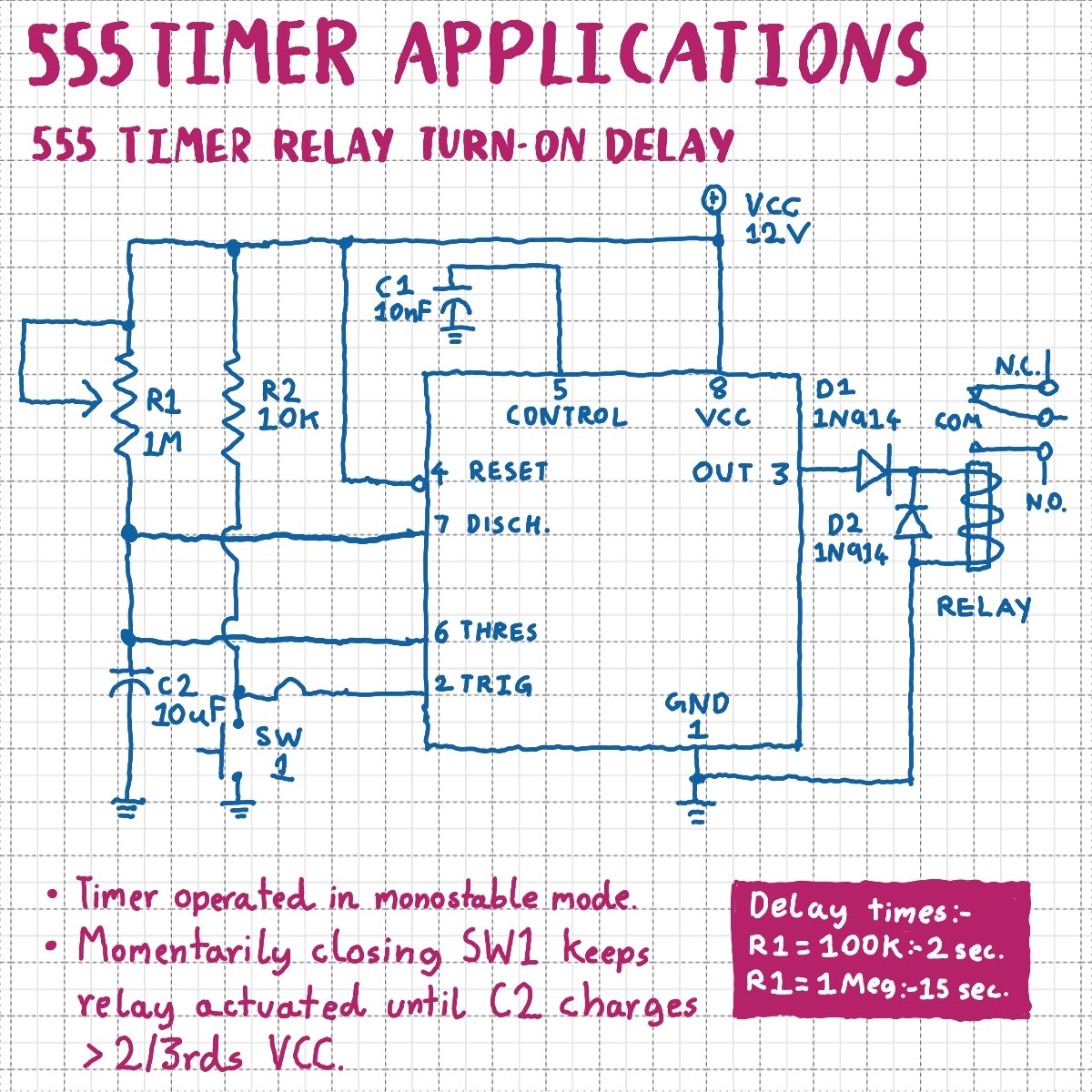
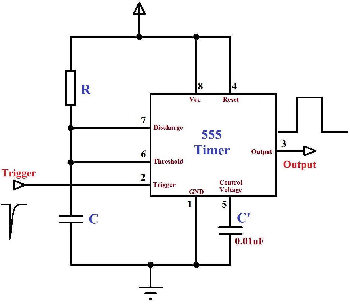
In monostable mode, the circuit remains in a stable low state until an external trigger pulse pulls the trigger pin (Pin 2) below one-third of $V_{CC}$. Upon triggering, the output goes high for a predetermined period, after which it automatically returns to the low state and waits for the next trigger. This mode is used for touch switches, burglar alarms, and delayed turn-off timers.
The duration of the output pulse ($t$) is governed by a single resistor and capacitor pair:
$$t = 1.1 \times R \times C$$
3. Bistable Mode (Flip-Flop Switch)
In bistable mode, the 555 acts as a basic memory element or toggle switch. The threshold and trigger pins are held at specific bias voltages, and external pushbuttons independently set or reset the output state. This mode requires minimal external components and is useful for simple digital memory applications or manual relay control.
Popular 555 Timer Circuits Projects to Build
Building practical projects bridges the gap between theoretical knowledge and hands-on competence. The following projects represent classic applications of the 555 timer, categorized by complexity and operating mode.
| Project Name | Operating Mode | Primary Components | Typical Application |
|---|---|---|---|
| LED Flasher | Astable | NE555, Resistors ($1,\text{k}\Omega$, $100,\text{k}\Omega$), Capacitor ($10,\mu\text{F}$), LED | Visual indicators, warning lights, decor |
| Adjustable PWM Motor Controller | Astable | NE555, Potentiometer, Diodes (1N4148), MOSFET | Controlling DC motor speed or LED brightness |
| Push-Button Timer (One-Shot) | Monostable | NE555, Pushbutton, Resistor, Capacitor, Relay | Staircase lighting timer, automated exposure units |
| Continuity Tester / Buzzer | Astable / Bistable | NE555, Piezo Buzzer, Current-limiting resistors | Testing wiring harnesses, printed circuit boards |
| Simple Metronome | Astable | NE555, Potentiometer, Speaker, Capacitor | Timing practice tool for musicians |
Project 1: Adjustable LED Flasher Circuit (Astable Mode)
This foundational project introduces the astable configuration. By replacing one of the fixed resistors with a potentiometer, you can dynamically alter the blink rate of an LED.
- Connect Pin 8 ($V_{CC}$) and Pin 4 (Reset) to the positive power rail ($9\text{V}$).
- Connect Pin 1 (Ground) to the negative power rail.
- Jumper Pin 2 (Trigger) directly to Pin 6 (Threshold).
- Connect a $10,\mu\text{F}$ electrolytic capacitor from Pin 6 to Ground.
- Place a $1,\text{k}\Omega$ resistor ($R_1$) between Pin 7 (Discharge) and the positive rail.
- Place a $100,\text{k}\Omega$ potentiometer or fixed resistor ($R_2$) between Pin 7 and Pin 6.
- Connect an LED in series with a $330,\Omega$ current-limiting resistor from Pin 3 (Output) to Ground.
- Apply power to observe the LED pulsing at a rate determined by your resistance and capacitance values.
Project 2: PWM DC Motor Controller
Controlling the speed of a direct current motor requires varying the average voltage delivered to the load without sacrificing torque. A pulse-width modulation (PWM) circuit built around an NE555 achieves this efficiently.
In this circuit, the astable configuration is modified by adding two fast-switching diodes (such as 1N4148) across the potentiometer terminals. This splits the charge and discharge paths of the timing capacitor, allowing you to alter the duty cycle of the output square wave from near 0% to nearly 100% while keeping the operating frequency relatively constant. Because the 555 output pin can source or sink a maximum of $200,\text{mA}$, you must connect the output of the timer to the gate of an N-channel power MOSFET (such as an IRF520) to safely drive a high-current DC motor.
Project 3: Touch-Activated Timer Switch (Monostable Mode)
Demonstrating the extreme sensitivity of the 555's trigger pin, this project creates a switch that activates an output device for a fixed duration when touched by a human finger.
- Configure the 555 in monostable mode with a timing resistor of $1,\text{M}\Omega$ and a capacitor of $10,\mu\text{F}$, yielding an output pulse of approximately 11 seconds.
- Connect a small piece of copper wire or foil to Pin 2 (Trigger) to act as a touch pad.
- Ensure a pull-up resistor ($10,\text{k}\Omega$) connects Pin 2 to the positive rail so the trigger pin remains high under normal conditions.
- When a user touches the pad, stray electromagnetic interference and body capacitance pull the trigger pin low momentarily, initiating the timing cycle and turning on an attached relay or LED indicator for the specified duration.
Troubleshooting Common 555 Circuit Issues
Even experienced electronics builders occasionally encounter circuits that fail to operate as expected. Systematic troubleshooting saves time and prevents component damage.
- Completely Inactive Output: Verify that power connections to Pin 8 and Pin 1 are secure and that the supply voltage matches the operating limits of your IC variant. Check that the Reset pin (Pin 4) is not accidentally tied to Ground, as this forces the output low regardless of other inputs.
- Stuck High or Stuck Low Output: If the output remains permanently high or low, inspect the timing network (resistors and capacitors). A short-circuited capacitor or an open resistor on Pin 6 or Pin 2 will prevent the internal comparators from changing the state of the flip-flop.
- Excessive Heat Generation: If the 555 IC becomes hot to the touch, disconnect power immediately. This indicates a short circuit on the output pin (often caused by driving a heavy load directly without a buffer transistor) or a reversed power supply connection.
- Erratic Triggering: In monostable circuits, noise on the trigger pin can cause false triggering. Add a small decoupling capacitor ($0.1,\mu\text{F}$) between the power rails close to the IC and ensure proper pull-up resistors are installed on trigger inputs.
Frequently Asked Questions
What is the difference between an NE555 and a CMOS 555 timer?
The classic NE555 uses bipolar junction transistor (BJT) technology, which draws higher quiescent current and can source or sink up to $200,\text{mA}$ of output current. CMOS variants (such as the TLC555 or ICM7555) use field-effect transistors, resulting in extremely low power consumption, higher input impedance, and the ability to operate at lower supply voltages, making them ideal for battery-operated devices.
Can a 555 timer drive a relay directly?
Standard bipolar 555 timers can source or sink up to $200,\text{mA}$, which is theoretically enough to drive many small $5\nabla$ or $12\nabla$ electromechanical relays. However, doing so requires placing a flyback diode across the relay coil to absorb inductive kickback. For larger relays or heavy loads, using a transistor or MOSFET driver stage is strongly recommended to protect the IC.
How do I calculate the exact resistor and capacitor values for my desired time delay?
To determine component values for a monostable circuit, use the formula $t = 1.1 \times R \times C$, where $t$ is time in seconds, $R$ is resistance in ohms, and $C$ is capacitance in farads. Select a practical capacitor value first based on what is available in your components kit, and then calculate the required resistance.
Why is my 555 timer circuit output getting stuck high in astable mode?
This issue typically occurs if Pin 2 (Trigger) is not connected to Pin 6 (Threshold), or if the timing capacitor is damaged or improperly connected. In astable mode, both pins must share the capacitor node so that the capacitor voltage can continuously cross the internal one-third and two-thirds reference thresholds.
Can a 555 timer generate a pure sine wave?
No. The 555 timer fundamentally operates as a digital logic device, meaning its output switches sharply between high and low states, inherently producing square waves or rectangular pulses. To generate a sine wave, you must pass the square wave output through an external low-pass filter network or an operational amplifier integrator circuit.
Conclusion and Next Actions
Constructing 555 timer circuits projects provides an exceptional pathway to mastering analog and digital electronics fundamentals without the steep learning curve of microcontrollers. Begin your practical journey by assembling a basic astable LED flasher on a solderless breadboard to verify component functionality. Once you are comfortable with basic timing calculations, advance to more complex designs such as adjustable PWM motor drivers or touch-activated switches. Always verify your wiring against schematic diagrams before applying power, and consult datasheets when integrating higher-current output devices.