Controlling the speed of a 1 HP single-phase motor involves adjusting either the frequency of the power supply or the voltage delivered to the windings. For induction motors, Variable Frequency Drives (VFDs) are the most efficient method, while universal motors utilize simple voltage regulation. Success depends on matching the controller to the specific motor type—such as Permanent Split Capacitor (PSC) or Capacitor Start—to avoid overheating or torque failure.
The 1 HP (horsepower) single-phase motor is a workhorse in residential, commercial, and light industrial applications. You will find them powering everything from well pumps and conveyors to workshop lathes and ventilation fans. Unlike their three-phase counterparts, which are inherently balanced and easier to manipulate, single-phase motors present unique challenges for speed regulation due to their reliance on capacitors and centrifugal switches.
As of 2026, advancements in power electronics have made precision speed control more accessible, but the fundamental physics remains unchanged. To control these motors safely and effectively, one must understand the relationship between magnetism, frequency, and mechanical load.
The Core Physics: How Speed is Determined
To understand how to control the speed, we must first understand what determines the "natural" speed of a 1 HP motor. For an AC induction motor, the synchronous speed is calculated using a specific formula:
Speed (RPM) = (120 × Frequency) / Number of Poles
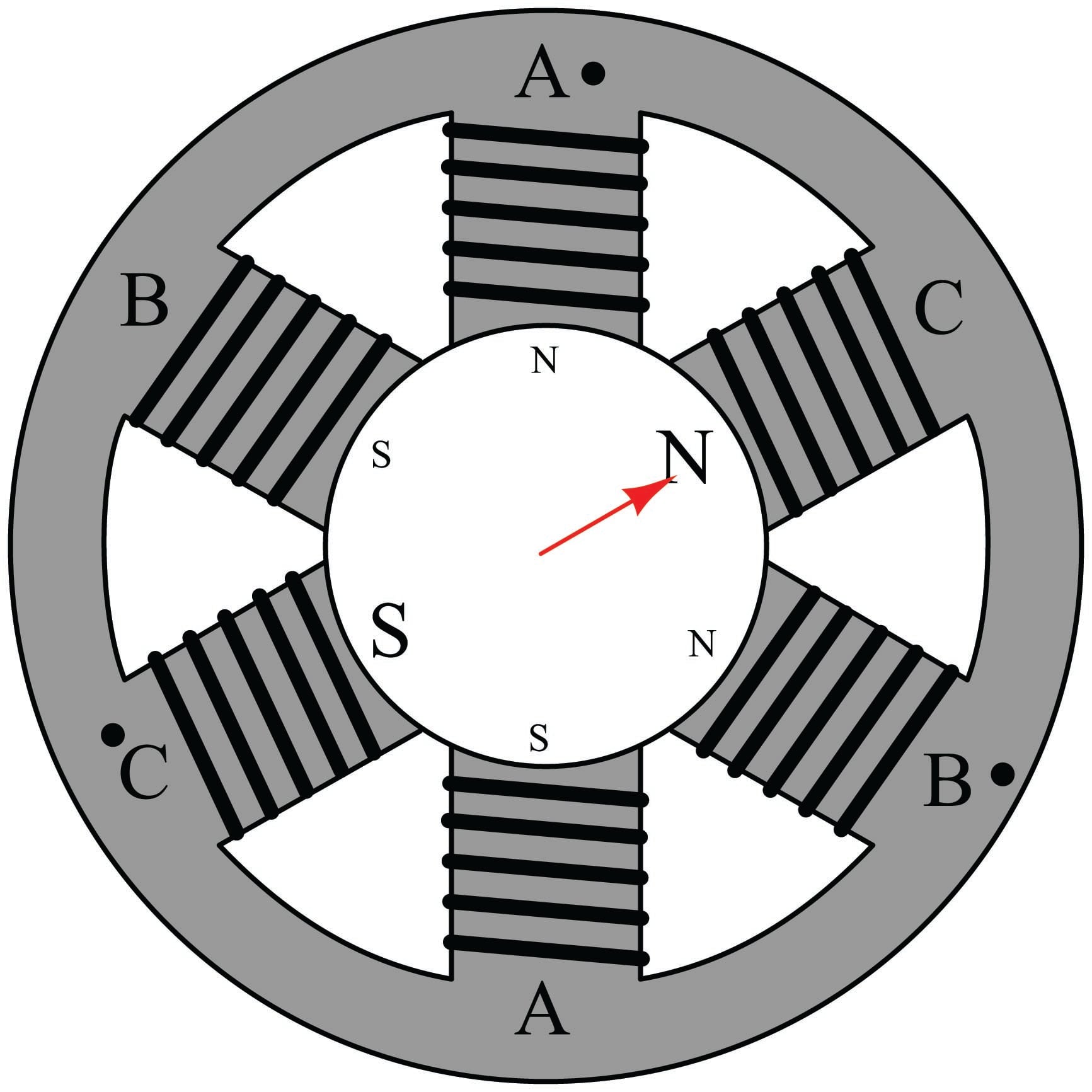
In a standard 60Hz environment, a 2-pole motor has a synchronous speed of 3,600 RPM, while a 4-pole motor runs at 1,800 RPM. However, induction motors never actually hit these speeds; they "slip" slightly behind the magnetic field to generate torque. A 1 HP motor labeled 1,725 RPM is a 4-pole motor experiencing slip.
Speed control works by manipulating the variables in this equation or by intentionally increasing the "slip" through voltage reduction.
The Role of Torque and Horsepower
A 1 HP motor provides approximately 746 Watts of power. Horsepower is a function of torque and speed (HP = Torque × RPM / 5252). When you reduce the speed of a motor, maintaining the necessary torque becomes the primary challenge. If you slow a motor down but the load requires the same amount of turning force, the motor must draw more current, which generates heat. Without adequate cooling—often provided by a fan attached to the motor's own shaft—the motor will eventually burn out its insulation.
Identifying Your Motor Type: The Prerequisite for Control
Before selecting a control method, you must identify the internal configuration of your 1 HP motor. Not all single-phase motors are compatible with all controllers.
1. Permanent Split Capacitor (PSC) Motors
PSC motors are common in HVAC blowers and fans. They use a run capacitor that remains in the circuit at all times. These are the most "controllable" single-phase induction motors. They can handle both voltage-based speed controllers (like Triacs) and specialized single-phase VFDs.
2. Capacitor Start / Induction Run (CSIR)
These motors use a high-capacitance start capacitor to get the motor spinning, which is then disconnected by a centrifugal switch once the motor reaches about 75% of its rated speed. Warning: These are extremely difficult to control via voltage reduction. If the speed drops too low, the centrifugal switch will close again, re-engaging the start winding, which is not rated for continuous duty and will quickly burn out.
3. Capacitor Start / Capacitor Run (CSCR)
Similar to the CSIR but with an additional run capacitor for better efficiency. These are common in high-torque 1 HP applications like air compressors. Like the CSIR, the presence of the centrifugal switch makes speed control via frequency or voltage very risky without specialized equipment.
4. Universal Motors
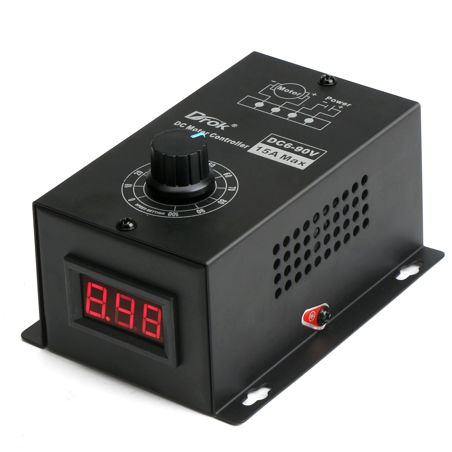
Found in portable power tools (routers, drills) and vacuums, these motors use brushes and can run on AC or DC. These are the easiest to control using simple pulse-width modulation (PWM) or Triac-based dimmers.
Primary Methods of Speed Control in 2026
The technology used to control a 1 HP motor has evolved significantly, with digital processing allowing for smoother curves and better motor protection.
Variable Frequency Drives (VFDs)
A VFD is the gold standard for induction motor control. It works by converting the incoming AC power to DC, and then "inverting" it back into a simulated AC wave at a different frequency.
- How it Works: By changing the frequency (Hz) from 60Hz down to 30Hz, you effectively cut the synchronous speed in half.
- The V/f Ratio: To maintain torque without saturating the motor’s magnetic core, the VFD also reduces the voltage in proportion to the frequency. This is known as the Volts-per-Hertz ratio.
- Single-Phase Limitations: Standard VFDs are designed for three-phase motors. While "Single-Phase to Single-Phase" VFDs exist for 1 HP motors (specifically for PSC and Shaded Pole types), they are more expensive and complex. You cannot typically use a standard 3-phase VFD on a single-phase motor because the VFD's output phase-angle will not align with the motor's capacitor-run design.
Triac-Based Voltage Regulation
Often called "solid-state speed controllers," these are similar to heavy-duty light dimmers.
- How it Works: The Triac "chops" the AC sine wave, reducing the total RMS voltage delivered to the motor. This increases the slip, causing the motor to slow down.
- Best Use Case: This method is only effective for loads where the torque requirement drops significantly with speed, such as centrifugal fans or pumps. It is poorly suited for 1 HP motors driving "constant torque" loads like conveyors or compressors.
- Heat Issues: Because the motor is slipping more, it generates significant internal heat.
Autotransformers
Unlike Triacs, which chop the waveform and create electrical noise (harmonics), an autotransformer reduces the voltage by using different "taps" on a coil to provide a clean, lower-voltage sine wave. This is a robust, albeit bulky, way to control the speed of PSC motors without the electromagnetic interference (EMI) associated with digital controllers.
Mechanical Speed Control
Sometimes the best way to control a 1 HP motor's speed isn't electrical at all.
- Pulleys and Belts: By changing the ratio of the drive pulley to the driven pulley, you can reduce the output speed while increasing the torque. This is the preferred method for drill presses and lathes.
- Gear Reductions: A 10:1 gearbox will turn a 1,725 RPM motor into a 172.5 RPM output shaft with nearly ten times the torque.
Comparison of Speed Control Methods for 1 HP Motors
| Method | Best Motor Match | Torque Retention | Complexity | Efficiency |
|---|---|---|---|---|
| VFD (Frequency) | PSC / Shaded Pole | Excellent | High | High |
| Triac (Voltage) | Fan/Blower PSC | Poor | Low | Low |
| Autotransformer | PSC / Induction | Moderate | Medium | Medium |
| Mechanical (Pulley) | All Types | Superior | Low | High |
| PWM (DC/Universal) | Universal Motors | Good | Medium | High |
Technical Implementation: Step-by-Step for 1 HP Motors
If you are looking to implement a speed controller for a 1 HP motor in a workshop or industrial setting, follow these steps to ensure safety and equipment longevity.
Step 1: Verify Nameplate Data
Check the motor nameplate for the following:
- FLA (Full Load Amps): Your controller must be rated for at least 1.25 times the FLA. A 1 HP 115V motor typically draws around 16 Amps; a 230V model draws about 8 Amps.
- Service Factor (SF): A motor with a higher SF (e.g., 1.15) handles the heat of speed control better than one with 1.0.
- Insulation Class: Look for Class F or H insulation if you plan on running at low speeds frequently.
Step 2: Choose the Controller
If the motor is a Universal motor (it has brushes), use a simple 20A Router Speed Controller. If it is a PSC motor on a fan, use a dedicated single-phase AC motor speed controller. If it is a Capacitor Start motor, consider replacing the motor with a 3-phase motor and a 1-phase-to-3-phase VFD, as this is often cheaper and more reliable than trying to control a 1-phase CSIR motor.
Step 3: Wiring and Safety
Single-phase motors involve high-current capacitors that can hold a charge even when the power is off.
- Ensure the controller is grounded to the motor frame.
- Install a physical disconnect switch within sight of the motor.
- If using a VFD, use shielded cable to prevent the high-frequency switching from interfering with other electronics (like sensors or Wi-Fi).
Step 4: Setting the Minimum Speed
Never set a controller to 0% for an induction motor. Most 1 HP motors require a minimum speed (usually 20-30%) to keep the internal cooling fan moving enough air to prevent the windings from melting. In 2026, many digital controllers allow you to "clamp" the bottom end of the speed range to prevent accidental damage.
Common Pitfalls and Troubleshooting
The "Humming" Motor
When using voltage-reduction controllers (Triacs), the motor may emit a loud hum or buzz. This is caused by the distorted AC waveform. If the humming is excessive, it indicates the motor is under high stress and may fail. Switching to an autotransformer or VFD usually resolves this.
Failure to Start
A 1 HP motor requires a "breakaway torque" to begin moving the load. If the speed controller is set too low at startup, the motor may hum and stay stationary. This is a "stalled" condition. The current will skyrocket, and the motor will burn out in seconds. Modern VFDs have a "boost" feature to provide extra voltage at the start to overcome this.
Overheating at Low Speeds
Because 1 HP motors are often "Totally Enclosed Fan Cooled" (TEFC), the cooling fan is attached to the motor shaft. If you run the motor at 25% speed, the fan also runs at 25% speed, which provides almost zero airflow. If you must run at low speeds for long periods, you may need to mount an external, constant-speed electric fan to blow air over the motor casing.
Frequently Asked Questions
Can I use a standard light dimmer for a 1 HP motor?
No. A standard household light dimmer is usually rated for 600 Watts (approx. 0.8 HP) and is designed for resistive loads, not inductive motor loads. Using a light dimmer on a 1 HP motor will likely cause the dimmer to overheat and fail, or it may destroy the motor's capacitors due to the "dirty" power signal.
Why is it harder to control a single-phase motor than a three-phase motor?
Three-phase motors create a naturally rotating magnetic field. Single-phase motors create a pulsating field that doesn't "rotate" until a second phase is simulated by a capacitor or a start winding. This secondary circuit makes the motor's electrical characteristics change as it speeds up, which interferes with simple frequency or voltage adjustments.
Does slowing down the motor save electricity?
In centrifugal applications (fans and pumps), yes. According to the "Affinity Laws," power consumption is proportional to the cube of the speed. Reducing a fan's speed by 20% can nearly halve the energy consumption. However, for constant torque loads (like a winch), the energy savings are minimal because the motor must still work just as hard to move the weight.
Can I use a VFD on a motor with a centrifugal switch?
Generally, no. If the VFD slows the motor below the "switch-in" point, the start winding will engage while the motor is running. This creates a massive heat spike and can lead to capacitor explosion or winding failure. For these motors, mechanical speed control is the only safe option.
What is the best way to control a 1 HP lathe motor?
For a 1 HP workshop lathe, a step-pulley system is the most reliable. If you want "infinitely variable" speed, the best 2026 practice is to replace the single-phase motor with a 1 HP three-phase motor and use a single-phase input VFD. This provides full torque at almost any speed and is the industry standard for modern machining.
Final Recommendation
When dealing with a 1 HP single-phase motor, the "how it works" of speed control is a balance between electrical frequency and thermal management. If your application involves a fan or a pump with a PSC motor, a specialized single-phase VFD or a high-amperage solid-state controller is the most effective solution.
For high-torque machinery like compressors or conveyors using Capacitor-Start motors, avoid electrical speed control entirely. Instead, utilize pulleys, belts, or gear reducers to achieve the desired output speed. This preserves the motor’s torque and ensures that the internal centrifugal switch and start windings are not compromised, extending the life of your equipment well into the future.