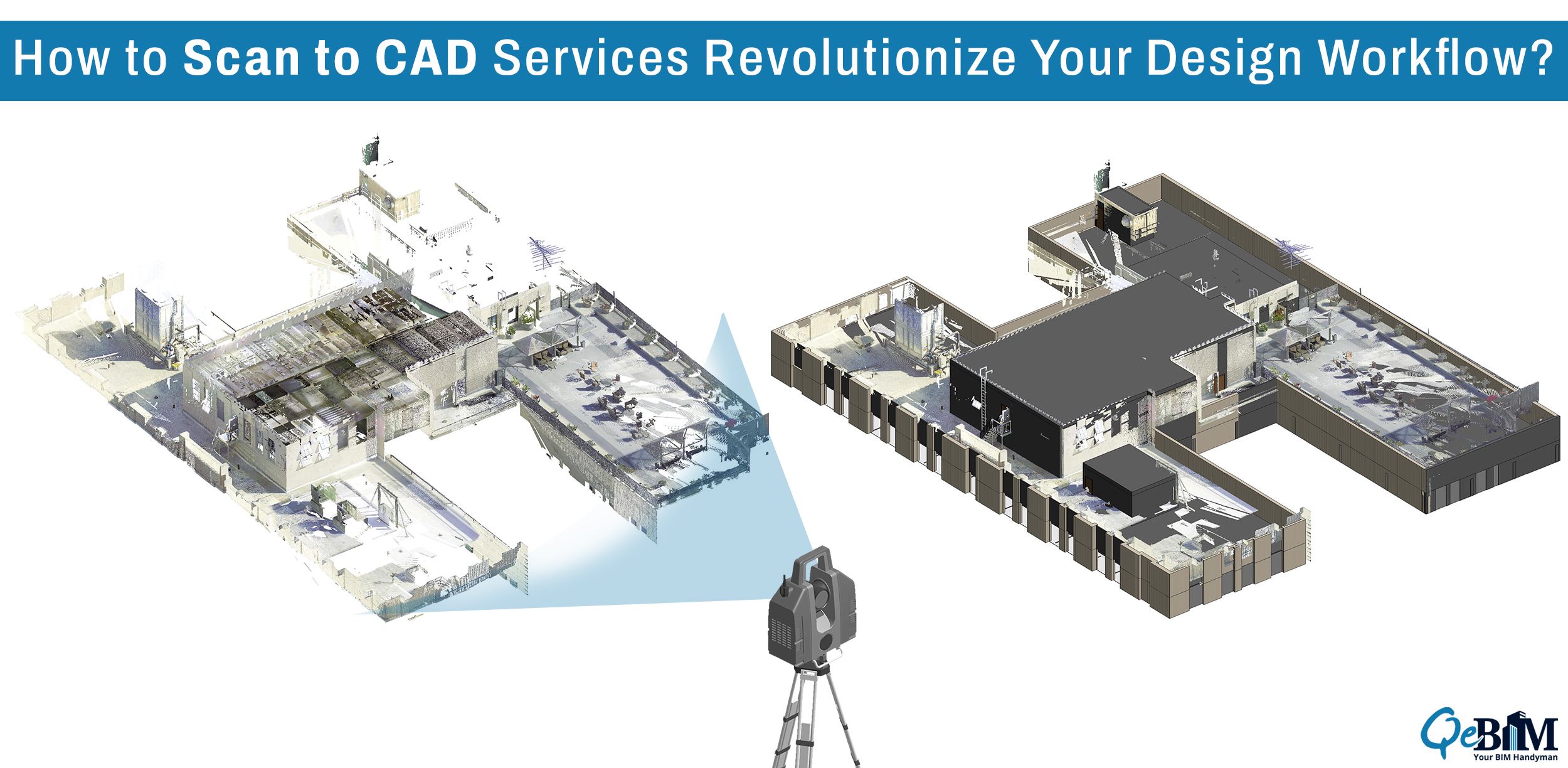
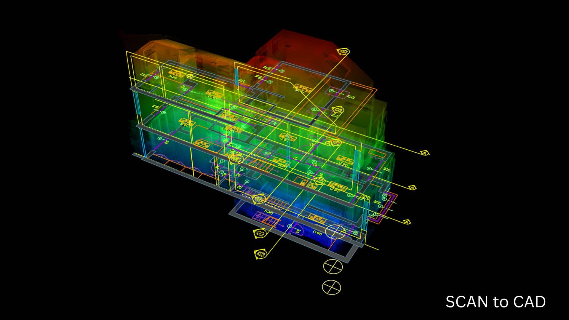
Integrating 3D scanning into computer-aided design (CAD) workflows bridges the physical and digital worlds, allowing engineers and designers to capture real-world geometry, convert it into digital point clouds or polygon meshes, and rebuild or modify it inside parametric modeling environments for rapid prototyping, manufacturing, and quality inspection.
The Evolution of Digital Prototyping and Reverse Engineering
The traditional design lifecycle relied heavily on manual measurements, 2D blueprints, and time-consuming manual 3D modeling from scratch. While parametric CAD software revolutionized precision manufacturing, it frequently encountered a bottleneck when dealing with organic shapes, legacy parts without digital documentation, or physical prototypes modified by hand. The evolution of optical, laser, and structured-light 3D scanning has fundamentally altered this paradigm. By capturing millions of coordinate points—known as a point cloud—in a matter of seconds, engineers can replicate complex physical geometry with sub-millimeter accuracy.
However, capturing a physical object is only the first step. A raw point cloud or a dense triangular mesh is not immediately editable in a traditional parametric CAD package like SolidWorks, Autodesk Inventor, or CATIA. Traditional CAD relies on mathematical representations such as Non-Uniform Rational B-Splines (NURBS), boundary representations (B-rep), and feature trees. Bridging this gap requires sophisticated preprocessing, mesh segmentation, and reverse engineering (RE) workflows. Today, modern design environments integrate these steps more fluidly, minimizing data loss and dramatically accelerating the transition from physical artifacts to fully editable parametric assemblies.
Core Technologies: How 3D Scanners Capture Physical Geometry
To understand how 3D scan data integrates into modern design, it is essential to examine the underlying capture technologies. Different hardware mechanisms suit different materials, scales, and accuracy requirements.
- Structured-Light Scanning: Projecting a series of linear patterns onto an object's surface allows cameras to triangulate deformations and calculate depth. This method delivers exceptionally high detail and fast capture speeds, making it ideal for medical devices, consumer electronics, and small-to-medium industrial parts.
- Laser Triangulation (Handheld and Automated): Emitting a laser line across an object while optical sensors track its reflection offers robust performance on shiny, dark, or reflective surfaces, especially when paired with specialized scanning sprays. Handheld laser scanners provide immense flexibility for capturing parts directly on the factory floor or inside vehicles.
- Terrestrial and Mobile LiDAR: Operating on time-of-flight or phase-shift principles, these systems measure large environments, buildings, and massive infrastructure. While terrestrial scanners capture dense architectural point clouds, integrating this data into architectural information modeling (AIM) and civil CAD pipelines follows similar data-reduction principles as mechanical reverse engineering.
| Scanner Type | Primary Technology | Best Suited For | Typical Accuracy |
|---|---|---|---|
| Structured Light | Projected fringe patterns | Organic shapes, electronics, small molds | High (0.01mm – 0.05mm) |
| Handheld Laser | Laser lines & triangulation | Large machinery, automotive, on-site parts | Medium-High (0.02mm – 0.1mm) |
| Terrestrial LiDAR | Time-of-flight laser pulses | Factories, civil infrastructure, large spaces | Low-Medium (1mm – 5mm) |
The Data Pipeline: From Point Cloud to Parametric CAD
Transitioning a raw scan into a functional CAD model requires a structured sequence of software operations. Skipping or mishandling any stage in this pipeline introduces errors that compound downstream during simulation, tooling design, or CNC machining.
1. Point Cloud Cleaning and Alignment
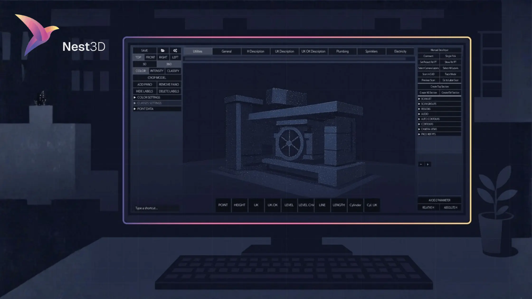
Raw scans often contain extraneous environmental data, sensor noise, and overlapping viewpoints. Operators use scanning software (such as PolyWorks, Geomagic Control X, or GOM Inspect) to remove outliers, smooth out noise, and align multiple scans into a single, cohesive coordinate system using target markers or geometric best-fit algorithms.
2. Polygon Mesh Generation
Once the point cloud is cleaned, the software connects adjacent points to form a polygon mesh—typically composed of triangular facets (STL format). At this stage, hole-filling algorithms patch minor data dropouts caused by occlusions or deep recesses. The mesh represents the exact surface of the object but lacks parametric intelligence.
3. Mesh-to-CAD Conversion (Reverse Engineering)
This phase presents the most significant technical challenge. Designers can approach this in two ways:
- NURBS Surface Fitting (Freeform Modeling): For artistic, medical, or highly organic shapes (such as footwear, helmets, or turbine blades), software wraps a smooth, continuous patch network of NURBS surfaces over the mesh. This creates a visually accurate representation but sacrifices traditional feature-based history trees.
- Parametric Feature Reconstruction: For mechanical components with prismatic features, holes, fillets, and extrusions, designers use hybrid software environments (such as SpaceClaim, Geomagic Design X, or specialized CAD modules) to slice the mesh, extract cross-sectional sketches, and rebuild the part using standard parametric extrusion and revolution tools.
Key Applications in Modern Engineering and Design
The integration of 3D scanning and CAD powers innovation across numerous industrial sectors, streamlining workflows that were previously cost-prohibitive or technically impossible.
Quality Control and Inspection
In modern manufacturing, 3D scan data serves as the ultimate arbiter of quality. By superimposing a scan of a manufactured part directly onto the original CAD master model using color-mapped deviation analysis, quality engineers can instantly visualize dimensional variances, warping, sink marks, and tooling wear down to the micron level. This eliminates the need for slow, single-point coordinate measuring machine (CMM) inspections on complex freeform surfaces.
Legacy Part Reproduction and Maintenance
Many aerospace, automotive, and heavy machinery components remain in service for decades. When original manufacturer drawings are lost or obsolete, maintenance teams scan the worn or broken physical part, clean up the digital mesh, redesign it in CAD with optimized wall thicknesses or modern alloys, and manufacture a direct replacement via CNC machining or metal 3D printing.
Customization and Ergonomics
Human-centric design relies heavily on scan integration. Medical orthotics, prosthetics, helmets, and protective gear are customized to individual body geometries captured via non-invasive 3D body or limb scans. Designers then build comfortable, ergonomic enclosures directly around the human digital twin inside their CAD software.
Challenges and Technical Limitations
Despite significant software advancements, integrating 3D scan data into CAD workflows presents persistent operational hurdles.
- Data Density Management: High-resolution scanners generate massive mesh files containing tens of millions of polygons. Importing these directly into parametric CAD kernels can cause software crashes, slow down viewport rendering, and corrupt feature trees. Operators must judiciously decimate and retopologize meshes before exporting them to CAD.
- Loss of Intent: Reverse engineering reconstructs how a part looks, not necessarily why it was designed that way. A scanned cylinder captures its exact manufacturing imperfections, ovality, and surface roughness. Forcing a clean parametric CAD cylinder over an imperfect scan requires engineering judgment to determine nominal dimensions versus acceptable manufacturing tolerances.
- Skill Barrier and Software Costs: Mastering both metrology software and advanced parametric CAD integration demands specialized training. High-end hardware and enterprise software licenses represent a substantial capital investment for small-to-medium enterprises.
Best Practices for Seamless Scan-to-CAD Workflows
Maximizing efficiency requires adherence to standardized operational protocols from the scanning booth to the design desk.
- Define the End Use First: Do not capture higher resolution than necessary. An inspection workflow requires dense, un-smoothed surface data, whereas a conceptual styling workflow benefits from a lightweight, retopologized mesh.
- Plan Scan Strategy to Minimize Occlusions: Position targets and plan multiple scan angles to capture deep pockets, undercuts, and internal features before relying on software hole-filling algorithms.
- Utilize Hybrid CAD Environments: Leverage specialized reverse-engineering software packages that sit between metrology data and traditional CAD programs, allowing for smooth curve extraction and live transfer of feature trees.
Frequently Asked Questions
Can a 3D scan be opened directly as an editable CAD file?
No. 3D scanners capture meshes or point clouds consisting of coordinates and polygons, whereas CAD software relies on mathematical parametric features (equations, sketches, and extrusions). Converting a scan into a true editable CAD file requires a reverse-engineering step to rebuild the geometry using surfaces or parametric features.
What is the difference between a mesh file (STL) and a CAD file (STEP/IGES)?
An STL file represents a surface as a collection of interconnected triangles, which is great for 3D printing and visualization but difficult to modify parametrically. A STEP or IGES file contains precise mathematical boundary representations and NURBS curves, allowing engineers to alter dimensions, add holes, and modify features easily.
How accurate is 3D scan-to-CAD integration?
Accuracy depends primarily on the chosen scanning hardware, environmental conditions, and operator skill. Professional-grade industrial metrology scanners achieve volumetric accuracies within 0.02 mm to 0.05 mm, making them suitable for aerospace and automotive tolerance stack-ups.
Do I need specialized software to convert scans to CAD?
Yes. While some traditional CAD packages include basic mesh-handling tools, complex organic shapes and high-density point clouds typically require dedicated reverse-engineering software like Geomagic Design X, Dassault Systèmes Catia, or Siemens NX to bridge the gap effectively.
How does scan data assist with quality inspection?
By importing a scan of a manufactured physical part into inspection software and aligning it with the original CAD design, automated color maps highlight deviations, showing exact areas of positive or negative variance against manufacturing tolerances.
Conclusion and Next Actions
Integrating 3D scanning into modern design environments transforms how engineers capture, inspect, and modify physical reality. To implement this workflow successfully, begin by auditing your current design and manufacturing bottlenecks—whether they lie in legacy part reproduction, quality inspection, or ergonomic customization. Invest in appropriate hardware matched to your dimensional tolerances, train personnel on dedicated reverse-engineering software pipelines, and establish clear protocols for data management to ensure a smooth transition from physical artifact to intelligent digital model.