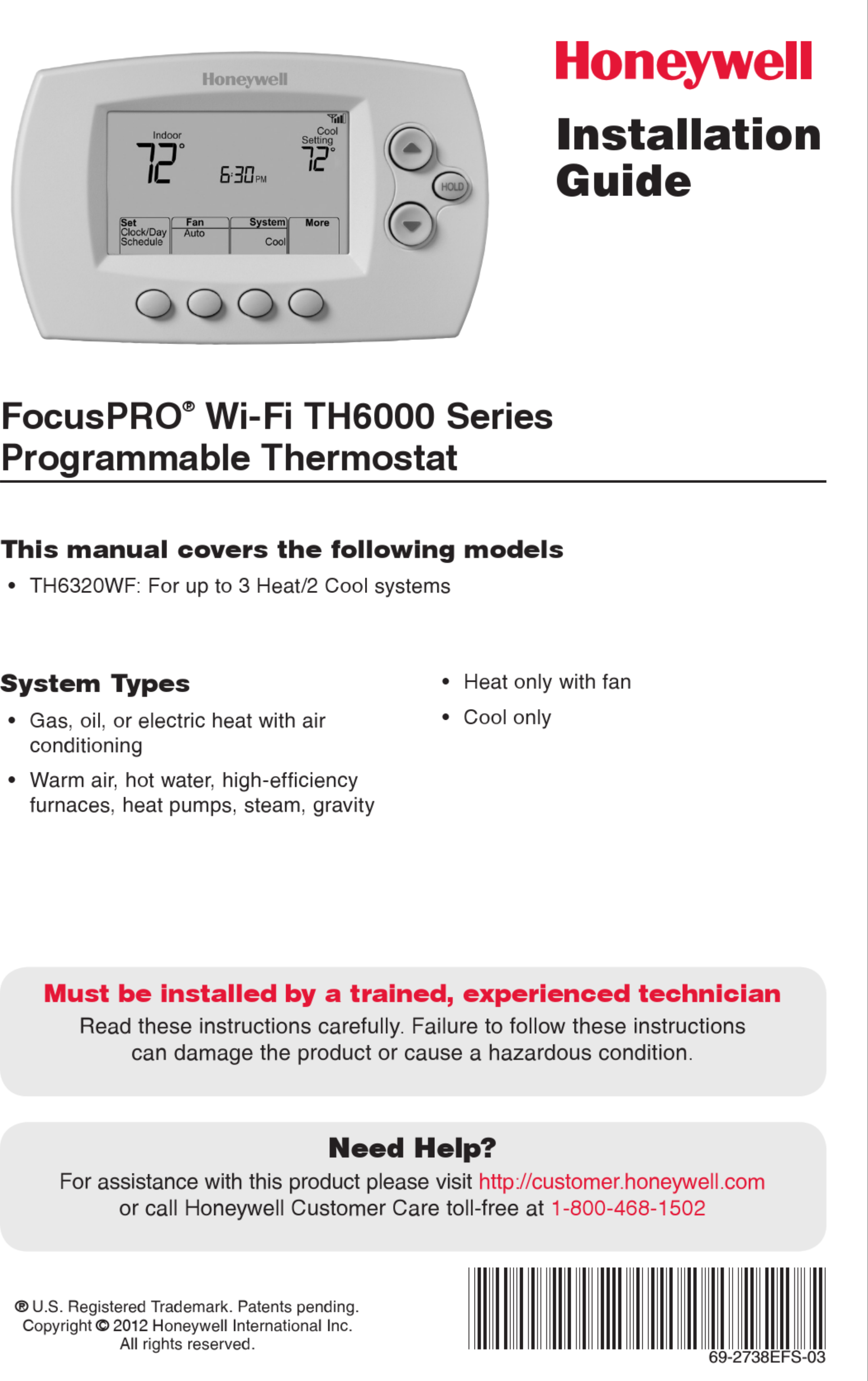
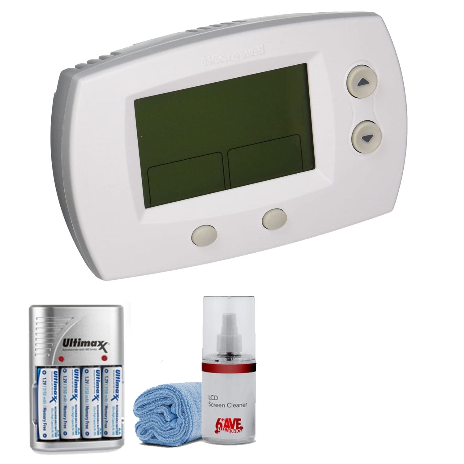
The Honeywell Pro 5000 is a non-programmable digital thermostat widely utilized for its reliability and straightforward operation. To successfully install or troubleshoot this device, you must rely on the official Honeywell installation manual, which provides the critical wiring diagrams and system configuration settings (Installer Setup) required to match the thermostat to your specific HVAC system’s voltage and stage requirements.
Understanding the Honeywell Pro 5000 Series
The Honeywell Pro 5000 (part of the FocusPRO 5000 series) is designed for simplicity. Unlike its sophisticated "smart" cousins, this device functions as a standard, manual-control digital interface. Its primary function is to replace older mechanical mercury-switch thermostats with a cleaner, more accurate, and battery- or hardwire-powered electronic display.
When searching for the "installation manual," you are essentially looking for the technical document that bridges the gap between your home’s low-voltage wiring and the thermostat’s backplate terminals. The device is versatile, supporting heat pumps, gas furnaces, oil furnaces, and electric cooling systems. However, because it can be configured for so many different types of heating and cooling, the "manual" is not just a set of assembly instructions—it is a configuration guide that determines how the device handles heat anticipators, cycle rates, and stage triggers.
Prerequisites for Installation
Before opening the manual or removing your current thermostat, you must ensure you have the necessary environment and tools. The Pro 5000 typically operates on 24VAC (alternating current), meaning it is part of a low-voltage circuit. Never attempt to install this on high-voltage (line voltage) systems like baseboard electric heaters, as doing so will destroy the unit and create a fire hazard.
Required Tools and Safety Gear:
- Precision Screwdriver Set: Required for the small terminals on the wall plate.
- Voltage Tester: To verify power is cut to the HVAC system at the breaker panel.
- Wire Strippers: In case existing wires are frayed or oxidized.
- Level: To ensure the unit sits flush against the wall for accurate temperature sensing.
- Camera or Adhesive Labels: To document the current wiring configuration before disconnection.
Before proceeding, locate your circuit breaker and turn off the power to both the furnace and the air conditioning unit. Do not rely on the thermostat itself to cut the power. Verify the power is off by attempting to change the set temperature or listening for the system to engage—it should remain silent.
Navigating the Installation Manual Sections
The official Honeywell documentation for the Pro 5000 is divided into specific sections that guide you through the mechanical, electrical, and logical setup. Understanding these segments is key to preventing system malfunctions.
1. Wall Plate Mounting
The manual emphasizes the importance of the wall plate. It serves as the terminal block for your system wires. If your wall has large holes from previous installations, use the included cover plate to ensure proper air circulation; drafts coming from inside the wall can trick the internal sensor, causing the thermostat to cycle the HVAC system incorrectly.
2. Terminal Identification and Wiring
This is the most critical section. The labels on your wires (usually R, W, Y, G, C) must correspond to the specific terminal designations on the Pro 5000.
- R and Rc: These are power terminals. If you have a single transformer system, a jumper (metal tab) is typically used to bridge these two.
- W/W2: Controls the heating.
- Y/Y2: Controls the cooling.
- G: Controls the fan relay.
- C (Common): Essential for powering the thermostat without relying solely on AA batteries.
3. Installer Setup (ISU) Menu
Many homeowners stop after mounting the device, but the "explained" part of the manual refers to the Installer Setup (ISU). This hidden menu allows you to tell the thermostat exactly what kind of heating equipment you have. If you configure a gas furnace but the thermostat thinks it is an electric heat pump, the system will not blow air correctly, or it may damage your heat exchanger.
Comparing Thermostat Configurations
The versatility of the Pro 5000 depends on how you interact with the ISU settings. Refer to the following table to understand how common system types influence the necessary setup.
| System Type | Wiring Required | ISU Setting Key | Impact on Operation |
|---|---|---|---|
| Gas/Oil Furnace | R, W, G, Y | Conventional | Allows the furnace to control its own fan if desired. |
| Electric Heat | R, W, G, Y | Conventional | Often requires the thermostat to trigger the fan immediately. |
| Heat Pump | R, Y, G, O/B | Heat Pump | Uses the O/B terminal for the reversing valve (cooling vs. heating). |
| Multi-Stage | R, W1, W2, Y1, Y2 | Staged | Manages auxiliary heat during extreme temperature drops. |
The "Common Wire" (C-Wire) Importance
A common point of confusion in the manual involves the "C" or Common wire. Many older homes were wired with only four wires (R, W, Y, G). The Pro 5000 can run on AA batteries, but it is highly recommended to use a C-wire if available. The C-wire provides continuous 24VAC power to the thermostat. Without it, the display may fade or the thermostat may fail to trigger the HVAC system reliably during high-load periods. If you lack a C-wire, you may consider a "C-wire adapter kit," but consult the manual or a technician before attempting to add one, as improper installation can blow the transformer on your furnace control board.
Troubleshooting Common Installation Errors
Even with the manual in hand, errors occur. Here is how to interpret the most frequent issues identified in the technical documentation:
No Display on Screen:
- Check the battery orientation.
- Ensure the thermostat is firmly snapped onto the wall plate.
- Verify the circuit breaker is ON.
- Check for a blown fuse on the furnace control board.
Heating or Cooling Won't Turn On:
- Verify your wire-to-terminal matching.
- Check the ISU settings to ensure you haven't selected a "Heat Pump" mode when you have a "Conventional" furnace.
- Listen for a "click" at the thermostat when the temperature demand is made. If you hear it, the thermostat is likely fine, and the problem lies with the furnace or contactor.
System Short Cycling:
- This is often an ISU setting issue regarding the "Cycle Rate." If the rate is set too high, the system turns on and off too frequently, which is inefficient. Adjust the cycle rate in the ISU menu to match the manufacturer's recommendation for your specific furnace type.
Maintenance and Long-term Reliability
By 2026, many Pro 5000 units have been in service for several years. Maintenance is minimal but essential for longevity. Replace the batteries annually, even if the unit is hardwired, to prevent leakage that can corrode the contact pins on the backplate. If the display begins to dim or you notice erratic temperature readings, check for dust buildup inside the housing, which can insulate the thermistor and cause a "drift" in accuracy.
Next Actions: Verification and Configuration
To finalize your installation, proceed as follows:
- Re-verify Wiring: Ensure no stray wire strands are touching adjacent terminals.
- Power On: Toggle the circuit breaker.
- Enter ISU: Refer to your manual to enter the setup mode (usually by holding specific buttons). Cycle through the ISU codes to ensure every setting matches your hardware.
- Test: Perform a "System Test" using the menu options to force the furnace and A/C to turn on for 30 seconds each.
If you find that your wiring does not match the diagrams provided in the manual—for instance, if you have non-standard wire colors or extra wires that you cannot account for—do not guess. The Honeywell Pro 5000 is designed for standard residential systems. If your home has a complex zoning system or proprietary communication protocols, this thermostat may not be compatible, and attempting a forced installation could lead to costly repairs for your furnace controller.