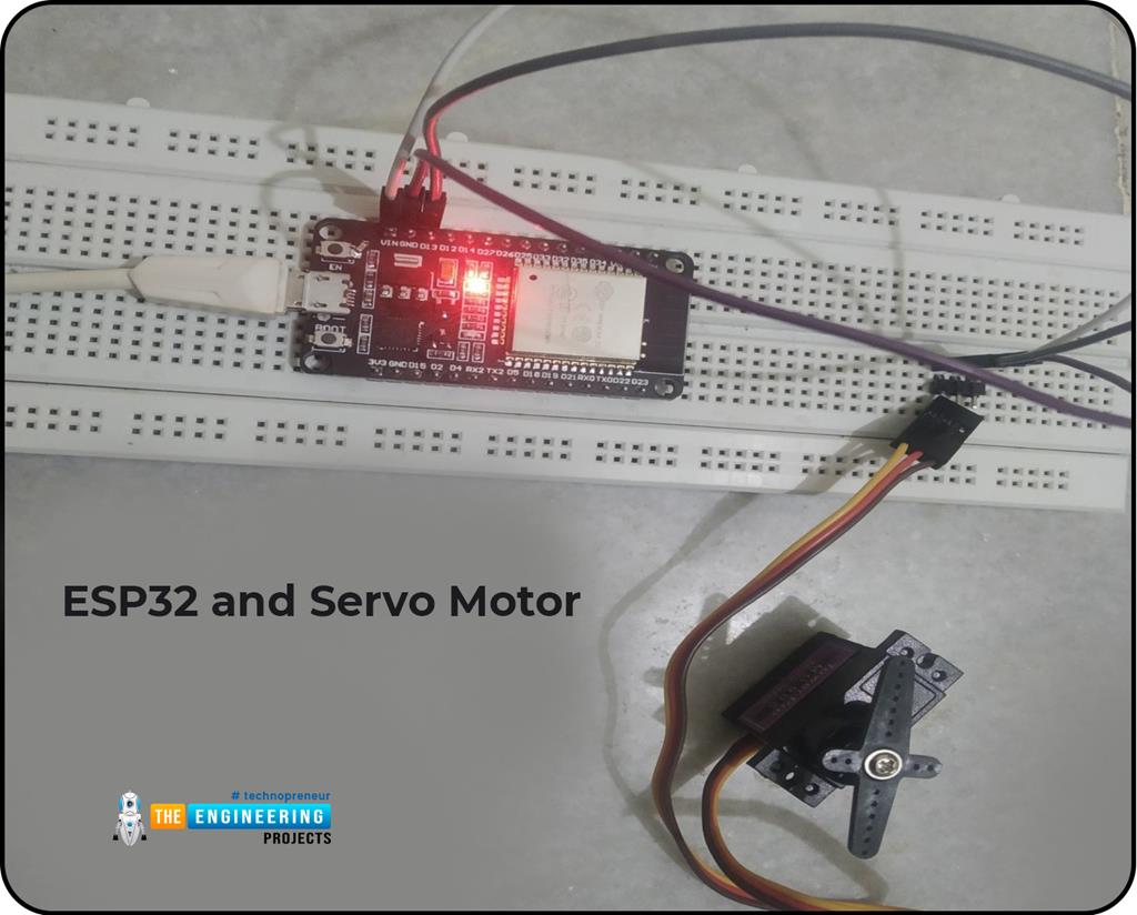
Controlling a servo motor with an ESP32 is a fundamental task for robotics and automation projects, requiring precise Pulse Width Modulation (PWM) to dictate the angular position of the motor's shaft. By leveraging the ESP32’s advanced LEDC peripheral or dedicated external drivers, you can achieve smooth, accurate motion across seven distinct implementation methods ranging from basic code-driven control to professional-grade hardware integration.
Understanding the Basics of Servo Control
Before selecting a method, it is essential to understand that standard hobby servos (such as the SG90 or MG996R) operate using a specific frequency—usually 50Hz, corresponding to a period of 20 milliseconds. Within that 20ms window, the ESP32 sends a pulse between 1ms and 2ms to determine position. The LEDC (LED Controller) peripheral on the ESP32 is the built-in hardware engine designed to generate these PWM signals efficiently, freeing up the CPU for other logic tasks.
1. Using the Built-in LEDC Peripheral
The most direct approach involves using the ESP32’s hardware LEDC peripheral. Because the ESP32 runs at 3.3V, while many servos prefer 4.8V to 6V, you must provide external power to the servo while sharing a common ground with the ESP32. You configure a specific channel, set the frequency to 50Hz, and calculate the duty cycle resolution. This method is the "gold standard" for internal control because it does not rely on libraries that block execution.
2. Utilizing the ESP32Servo Library
For developers working within the Arduino IDE environment, the ESP32Servo library provides a user-friendly abstraction layer. This library handles the complex register calculations for the LEDC peripheral, allowing you to use simple commands like myservo.write(angle). It is the most popular method for rapid prototyping because it supports multiple servos simultaneously across various GPIO pins without manual frequency calibration.
3. Integrating PCA9685 PWM Driver Boards
When your project scales beyond four or five servos, the number of available ESP32 pins becomes a constraint. A PCA9685 16-channel PWM driver board communicates with the ESP32 via the I2C protocol using only two wires (SDA and SCL). This offloads the PWM generation to the external chip, ensuring that even if the ESP32's processor is occupied by Wi-Fi or Bluetooth tasks, the servo signals remain jitter-free and stable.
4. Implementation via MicroPython
MicroPython is an excellent choice for those who prefer dynamic, interpreted languages over C++. Using the machine.PWM class, you can initialize a pin as a PWM output and set the frequency and duty cycle with minimal code. This method is particularly effective for IoT projects where you may need to update servo parameters over the air or via a web interface without needing to recompile and flash the firmware entirely.
5. Using the ESP-IDF Native Framework
For industrial or low-level applications where performance is critical, using the Espressif IoT Development Framework (ESP-IDF) provides the most control. By interacting directly with the LEDC driver APIs, you minimize latency and gain access to advanced features like fade functions and hardware-based duty cycle interpolation. This approach is recommended for complex robotics where thousands of movements occur per minute and timing consistency is non-negotiable.
6. Control via Blynk or Cloud Platforms
If you require remote operation, you can control your servo over the internet using a platform like Blynk. By integrating a slider widget in a mobile application, the ESP32 receives data packets via Wi-Fi and converts the input value into a PWM signal. This method combines network connectivity with physical motion, making it ideal for home automation projects, such as remote-controlled door locks or automated blinds.
7. Hardware-Level Interrupt-Driven Control
For high-precision applications requiring extreme responsiveness, you can use hardware interrupts coupled with a timer. By setting a high-resolution timer to trigger at specific intervals, you can manually toggle GPIO pins to generate the required pulse widths. While this is the most complex method, it allows for "jitter-less" performance in scenarios where standard PWM generation might suffer from overhead during heavy multi-threading.
Technical Comparison of Control Methods
| Method | Best For | Hardware Requirement | Complexity |
|---|---|---|---|
| LEDC Peripheral | Low-latency tasks | None | Medium |
| ESP32Servo Library | Quick Prototyping | None | Easy |
| PCA9685 Board | Multiple Servos | I2C Breakout | Medium |
| MicroPython | Rapid Iteration | None | Easy |
| ESP-IDF Native | Industrial/High Perf | None | High |
| Cloud (Blynk) | Remote Operation | Wi-Fi/Internet | Medium |
| Timer Interrupts | Custom Precision | None | High |
Essential Considerations for Success
Regardless of the method you choose, the most frequent failure point in servo projects is the power supply. A standard USB port from your computer often cannot provide enough current for multiple servos, leading to brownouts where the ESP32 resets unexpectedly. Always use a dedicated external power supply (typically 5V-6V) for the servos and ensure the ground wire is connected to the ESP32’s GND pin. Failing to share grounds will result in a floating reference voltage, causing erratic servo movement or permanent damage to the motor’s controller board.
Troubleshooting Common Issues
- Servo Jitter: If the servo arm shakes, check for unstable power supply or signal interference. Ensure your duty cycle calculations are not being interrupted by other high-priority tasks on the ESP32.
- No Movement: Verify the signal pin connection. Most servos require a 50Hz signal; if your frequency is set incorrectly (e.g., to 1kHz), the servo will either buzz or remain stationary.
- ESP32 Resets: This is almost always a power issue. Try adding a large electrolytic capacitor (e.g., 470µF to 1000µF) across the positive and ground terminals of the servo power input to smooth out current spikes.
Frequently Asked Questions
Can I power a servo directly from the ESP32 3.3V pin? No. While a single small servo might function briefly under light load, the 3.3V pin is not designed for the high current spikes servos demand. Always use an external 5V-6V power source to ensure stability and protect your ESP32.
What is the maximum number of servos an ESP32 can handle without external drivers? The ESP32 has 16 channels available for its LEDC peripheral. In theory, you can control 16 servos natively, but you must ensure your code architecture can handle the memory and processing requirements of generating that many simultaneous signals.
Why does my servo move to the wrong position when I power it on? This is typically a "start-up pulse" issue where the pin state is undefined before the ESP32 firmware fully initializes. You can mitigate this by adding a pull-down resistor on the signal line to ensure the pin stays low until the software takes control.
Is there a difference in pulse width requirements between servo brands? Yes. While most follow the 1ms (0°) to 2ms (180°) standard, some high-quality digital servos use wider ranges (e.g., 0.5ms to 2.5ms). Always consult the datasheet of your specific motor if it is not a standard hobby-grade unit.
Can I control a servo using an ESP32 over Bluetooth? Yes. You can use the ESP32's built-in Bluetooth Classic or BLE stack to receive signals from a smartphone and map those inputs directly to your PWM output functions using any of the methods described above.
Next Steps for Your Project
Once you have successfully achieved control using the ESP32Servo library as a baseline, begin integrating sensor data—such as input from a potentiometer or an ultrasonic distance sensor—to create a closed-loop system. Moving from a static movement to a sensor-responsive system is the transition point from simple electronics to true robotics. Start by mapping your sensor input to the servo’s angular range, ensuring you add constraints to protect the mechanical gears from reaching physical limits.