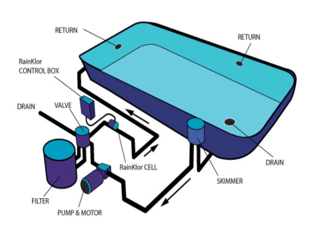
Mastering a pool filter installation diagram ensures proper water circulation, chemical distribution, and structural longevity for residential and commercial aquatic systems. Whether you are replacing an outdated sand filter, installing a new cartridge system, or upgrading to a high-efficiency DE (diatomaceous earth) unit, interpreting the schematic accurately prevents costly plumbing errors, pressure drops, and pump cavitation.
Installing a pool filter involves connecting the circulation system so that water flows from the pool skimmers and main drains, through the pump, into the filter tank, and back through the return jets or heater. The primary components include the pool pump, multi-port or push-pull valve, pressure gauge, air relief valve, and return lines. Success depends on precise pipe alignment, correct port labeling (pump, return, and waste), and adherence to manufacturer torque specifications for unions and bulkheads.
Understanding Pool Filtration Systems and Layouts
Before interpreting any pool filter installation diagram, you must understand the closed-loop hydraulic circuit of a swimming pool. Water is pulled out of the pool via suction lines (skimmers and main drains) by a centrifugal pump. The pump pushes water under pressure into the filter tank, where particulate matter is trapped by sand, filter fabric, or DE grids. Clean water then exits the filter, passes through any auxiliary equipment like heaters or chlorinators, and returns to the pool basin.
A standard pool installation diagram maps out this exact journey while accounting for safety components and maintenance bypasses. Misinterpreting the flow direction can rupture filter tanks, starve the pump of water, or damage expensive heating elements. Always verify the designated IN and OUT ports on your filter tank and valve body before cutting any PVC pipe.
Core Components Found in a Standard Diagram
- Pool Pump: The mechanical heart of the system, creating suction and pressure.
- Filter Tank: The vessel housing the media (sand, cartridge elements, or DE grids).
- Multiport or Slide Valve: Controls the directional flow of water for filtering, backwashing, rinsing, and wasting.
- Pressure Gauge: Measures internal tank pressure, indicating when backwashing or cleaning is necessary.
- Air Relief Valve: Bleeds trapped air out of the system during startup and after cleaning.
- Check Valves: Prevents backflow when the pump shuts down, maintaining the pump's prime.
Types of Pool Filters and Their Plumbing Variations
While the basic plumbing loop remains consistent, different filter technologies alter the specific layout of your installation diagram. Choosing the right filter type impacts footprint requirements, maintenance frequency, and water clarity standards.
- Pool Skimmers & Main Drains
- Centrifugal Pump
- Filter Tank (Sand/Cart/DE)
- Multiport Valve / Return Lines
- Heater / Sanitizer (Optional)
- Return Jets (Clean Water)
- Heater / Sanitizer (Optional)
- Multiport Valve / Return Lines
- Filter Tank (Sand/Cart/DE)
- Centrifugal Pump
Sand Filters
Sand filters use specially graded silica sand to trap debris down to 20–40 microns. Installation diagrams for top-mount or side-mount sand filters heavily feature a multiport valve. The valve features distinct ports labeled PUMP (from the pump discharge), RETURN (back to the pool), and WASTE (to drainage). Because sand filters require periodic backwashing to flush out trapped debris, the diagram will always display a waste line connection leading to a municipal drain, dry well, or lawn discharge point.
Cartridge Filters
Cartridge filters utilize porous polyester fabric cylinders to capture debris down to 10–15 microns. Because they do not require backwashing, cartridge filter installation diagrams are structurally simpler. They usually omit complex multiport valves in favor of a straightforward in-and-out configuration directly on the tank body, though an inline valve may be placed on the return line for maintenance isolation. Water enters the bottom or side of the tank, passes through the cartridge elements, and exits through the top port.
Diatomaceous Earth (DE) Filters
DE filters offer the highest filtration clarity, trapping particles down to 2–5 microns using a powdery fossilized algae medium coated over internal grids. The installation diagram for a DE filter closely mirrors that of a sand filter, utilizing either a multiport valve or a slide (push-pull) valve. Plumbers must pay close attention to the local environmental regulations governing DE backwash waste disposal, as many municipalities prohibit discharging DE powder directly into storm sewers.
Step-by-Step Preparation and Piping Layout
Proper preparation prevents structural leaks and ensures compliance with local electrical and plumbing building codes. Before applying any PVC primer or cement, dry-fit all components to verify alignment.
- Pad Placement: Ensure the equipment pad is level, poured concrete or compacted crushed stone, and elevated slightly above grade to prevent pooling water.
- Pump-to-Filter Distance: Position the pump close to the filter tank to minimize friction loss, keeping unions accessible for future motor or basket maintenance.
- Dry Fitting: Arrange the PVC schedule 40 pipes, elbows, and unions according to your filter diagram without glue. Mark alignment lines across joints with a waterproof marker.
- Union Placement: Install removable PVC unions before and after the pump and filter. This allows you to disconnect equipment easily during winterization or repair.
- Check Valve Integration: If your equipment pad sits significantly higher or lower than the pool water level, install a check valve on the suction side to maintain the pump prime.
Reading and Executing the Installation Diagram
When laying out your physical plumbing to match a pool filter installation diagram, precision and sequence are paramount. Rushing the glue phase can result in misaligned ports that place undue stress on threaded plastic bulkheads.
Connecting the Suction Side (Pool to Pump)
The suction side of the diagram runs from the pool skimmers and main drains to the front basket inlet of the pump.
- Use rigid Schedule 40 PVC pipe (typically 1.5-inch or 2-inch diameter).
- Avoid sharp 90-degree elbows directly before the pump inlet; maintain a straight run of pipe measuring at least 5 to 10 times the pipe diameter to ensure smooth water flow and prevent pump cavitation.
- Wrap all threaded male adapters with PTFE (Teflon) tape—typically 3 to 5 wraps—before screwing them into plastic pump housings. Hand-tighten plus a quarter-turn with strap wrenches to avoid cracking the housing.
Connecting the Pressure Side (Pump to Filter to Return)
The pressure side begins at the discharge port on top of the pump and leads to the filter tank inlet.
- Route the pipe from the pump discharge to the port marked PUMP or IN on the filter valve or tank.
- Run the pipe from the RETURN or OUT port toward the pool returns, incorporating any optional inline heaters, salt chlorinator cells, or chemical feeders only after the filtration stage.
- Ensure the pressure gauge is screwed securely into the top of the filter tank or multiport valve using thread sealant rated for plastic connections.
Comparative Analysis of Filter Installation Requirements
Choosing the correct filter installation path requires balancing physical space, upfront costs, maintenance efforts, and filtration performance.
| Filter Type | Filtration Fineness | Backwash Required? | Space Footprint | Typical Maintenance Effort |
|---|---|---|---|---|
| Sand | 20–40 Microns | Yes | Moderate | Low (Backwash weekly/biweekly; replace sand every 5-7 years) |
| Cartridge | 10–15 Microns | No | Compact | Medium (Remove and hose down elements every 4-6 weeks) |
| DE | 2–5 Microns | Yes | Large | High (Backwash and recharge with DE powder; annual grid inspection) |
Common Installation Mistakes and Troubleshooting
Even with a detailed pool filter installation diagram, installers frequently encounter operational issues due to minor oversights during assembly.
- Reversed Flow Ports: Connecting the pump discharge to the filter return port instead of the inlet port causes immediate pressure spikes, poor filtration, and potential damage to internal lateral assemblies or cartridges. Always double-check arrows on valve bodies.
- Over-Tightening Threaded PVC: Plastic threads expand and crack under excessive torque. Never use metal pipe wrenches on plastic fittings; use strap wrenches and thread tape exclusively.
- Inadequate Pipe Support: Unsupported PVC runs sag over time, putting heavy leverage stress on pump and filter bulkheads. Use pipe hangers and secure equipment pads to immobilize long runs.
- Air Leaks on Suction Side: If the pump fails to prime or spits air bubbles through the return jets, a suction-side joint is drawing air. Inspect union O-rings, pump lid gaskets, and pre-filter basket seals. Apply shaving cream around suspicious joints while the pump runs; if the noise changes or the cream gets sucked in, you have found your air leak.
Frequently Asked Questions
Can I install a pool filter and pump myself?
Yes, DIY installation is common for homeowners with basic PVC plumbing and electrical knowledge. However, hardwired 230V pool pumps require a licensed electrician to ensure compliance with local electrical safety codes and bonding requirements.
Which direction should water flow through a sand filter multiport valve?
Water must enter the port labeled PUMP (from the pump discharge), travel down through the sand bed inside the tank, and exit the RETURN port back toward the pool. Reversing these lines will fluidize and push sand directly into your pool return lines.
What is the purpose of the pressure gauge on a pool filter diagram?
The pressure gauge measures internal tank resistance. A clean filter establishes a baseline "clean operating pressure" (typically 10 to 20 PSI). When pressure rises 8 to 10 PSI above this baseline, it indicates the filter is loaded with debris and requires backwashing or cartridge cleaning.
Do I need check valves in my pool filter plumbing?
Check valves are necessary if your equipment pad is installed above the water level (to prevent losing prime) or if you have an attached spa that drains into a lower pool via gravity when the pump turns off.
How do I safely dispose of backwash water from a DE filter?
Check your local municipal codes regarding wastewater disposal. DE powder contains spent diatomaceous earth and organic pool waste. Many jurisdictions require routing backwash water to a sanitary sewer cleanout rather than a street storm drain.
Conclusion and Next Actions
Successfully executing a pool filter installation diagram relies on careful planning, exact alignment of suction and pressure lines, and strict adherence to manufacturer specifications. Begin by dry-fitting all PVC components, verify every valve port direction, and ensure unions are accessible for future maintenance. Once assembled, test the system thoroughly for leaks under pressure before securing permanent supports. If you encounter persistent priming issues or complex electrical wiring, consult a certified pool professional to safeguard your investment.