In Altium Designer, a library is a functional container for electronic component data, encompassing schematic symbols, PCB footprints, 3D models, and simulation parameters. Effective library management involves transitioning from legacy local files (SchLib, PcbLib) to modern, cloud-based Workspace components via Altium 365, ensuring data integrity, version control, and real-time supply chain synchronization across the design team.
Effective PCB design begins and ends with the quality of the component library. Without a verified, well-organized library, even the most advanced routing strategies can fail due to footprint mismatches or obsolete part selections. As of 2026, Altium Designer has solidified its ecosystem around the "Unified Component" model, which treats a component not just as a drawing, but as a digital twin of a physical part. This guide explores the architecture of Altium Designer libraries, how to create them, and the strategic advantages of moving toward managed content.
Understanding Library Types in Altium Designer
Before diving into creation, it is essential to distinguish between the various library formats supported by Altium Designer. The software has evolved through several iterations of library management, and while legacy formats are still supported for backward compatibility, modern workflows prioritize centralized, cloud-managed data.
Schematic and PCB Libraries (SchLib and PcbLib)
These are the foundational "source" libraries. A Schematic Library (.SchLib) contains the logical representation of the component (the symbol), while a PCB Library (.PcbLib) contains the physical landing pattern (the footprint) and 3D models. In a traditional workflow, these files are managed separately. While simple to create, they lack a formal link between the symbol and the footprint, requiring the user to manually map them within the schematic editor.
Integrated Libraries (IntLib)
An Integrated Library (.IntLib) is a compiled package that combines schematic symbols and PCB footprints into a single, read-only file. The primary advantage of an IntLib is portability; once compiled, the relationship between the symbol and the footprint is "locked," preventing accidental changes. This was the industry standard for many years, but it lacks the real-time update capabilities and revision history required for large, distributed teams in 2026.
Database Libraries (DbLib)
A Database Library (.DbLib) links Altium Designer to an external database (such as SQL, Oracle, or an Excel spreadsheet). In this model, the parameters (part numbers, values, descriptions) are stored in the database, while the symbols and footprints remain in standard Altium files. When a component is placed, Altium queries the database to populate the parameters. This is highly effective for companies that want to synchronize their CAD library with an internal ERP (Enterprise Resource Planning) or MRP (Material Requirements Planning) system.
Workspace Components (Managed Components)
Workspace components represent the current pinnacle of Altium library technology. Hosted on Altium 365 or an on-premise Enterprise Server, these are "managed" parts. They offer full revision control, lifecycle management (Draft, Released, Obsolete), and "Where Used" capabilities. If a footprint needs to be updated, you update it once in the Workspace, and Altium Designer identifies every project currently using that footprint, allowing for a controlled update process.
The Architecture of a High-Quality Component
A library entry is more than just a box with pins. In a professional environment, every component in your Altium Designer library should adhere to a strict structural standard to ensure manufacturability and clarity.
1. The Schematic Symbol
The symbol is the logical representation of the part. In 2026, best practices dictate that symbols should be organized by functional blocks rather than physical pin layouts (unless the part is a simple connector).
- Designator and Comment: Standardized prefixes (e.g., R? for resistors, U? for integrated circuits) are essential for Annotation tools.
- Electrical Pin Types: Correctly defining pins as Input, Output, Passive, or Power allows Altium’s Electrical Rule Check (ERC) to catch design errors early.
- Graphical Clarity: Symbols should follow a consistent grid (usually 100 mil) to ensure wires connect cleanly without offsets.
2. The PCB Footprint
The footprint is the physical interface between the component and the board. Precision here is non-negotiable.
- IPC Compliance: Most professional libraries use the IPC-7351 standard for land pattern calculations. This ensures that the solder fillets are appropriate for the chosen manufacturing class (Least, Nominal, or Most material condition).
- Courtyard Layer: A dedicated mechanical layer defining the "keepout" area around a component. This prevents components from being placed too close to one another, which would interfere with automated pick-and-place nozzles or manual rework.
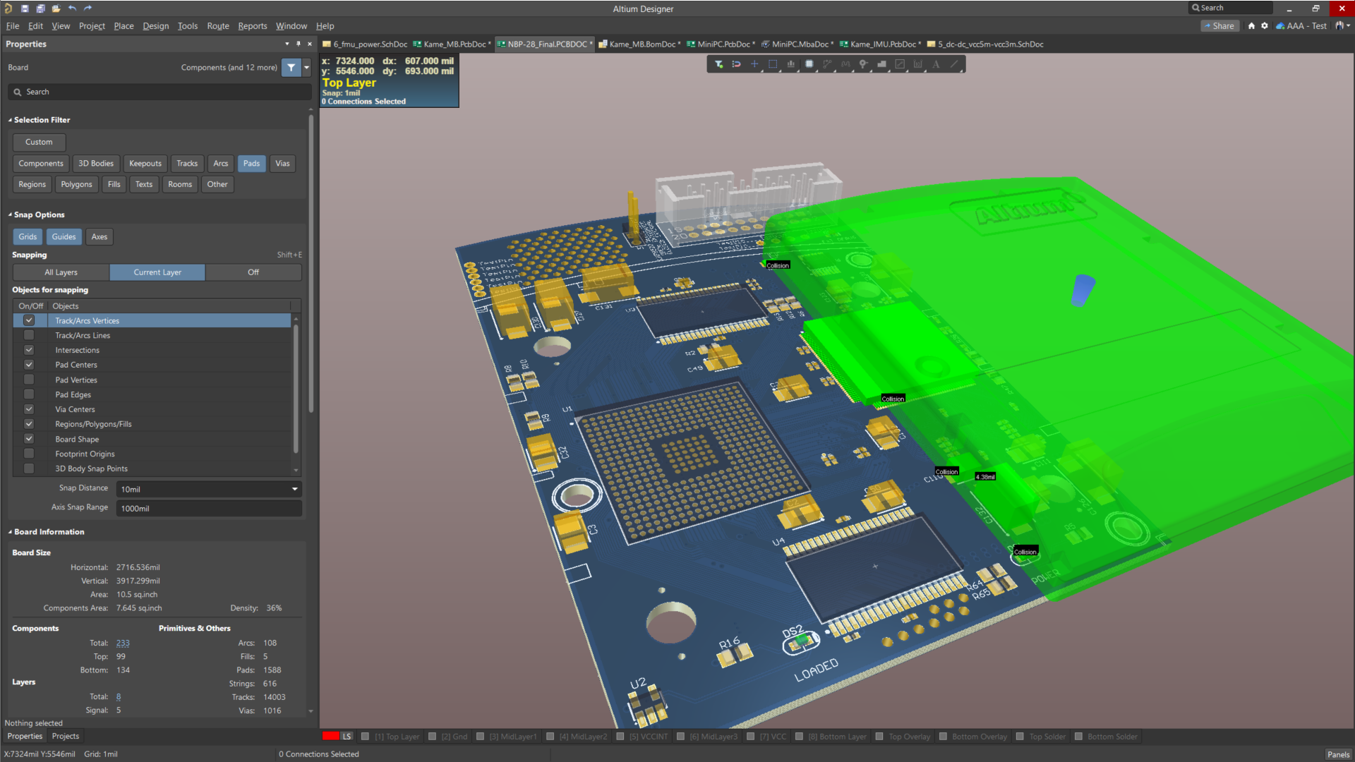
- 3D Models: Incorporating STEP or Parasolid files is now a requirement. 3D models allow for accurate MCAD-ECAD integration, enabling mechanical engineers to check for housing interferences or heat sink clearances before a single board is manufactured.
3. Component Parameters and Metadata
The "intelligence" of the library resides in its parameters. Beyond the basic value (e.g., 10k ohms), a robust library includes:
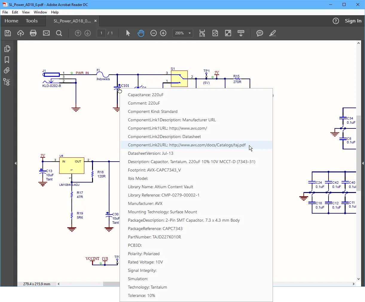
- Manufacturer Part Number (MPN): The primary key for procurement.
- Supplier Links: Direct integration with distributors like Digi-Key or Mouser via the Altium Manufacturer Part Search.
- Lifecycle Status: Is the part recommended for new designs, or is it approaching End-of-Life (EOL)?
- Compliance Data: RoHS, REACH, and Lead-Free status.
Comparison of Library Management Methods
| Feature | Local (SchLib/PcbLib) | Integrated (IntLib) | Database (DbLib) | Workspace (Altium 365) |
|---|---|---|---|---|
| Storage | Local Drive / Server | Local Drive / Server | SQL/Excel Database | Cloud (Altium 365) |
| Revision Control | Manual / File-based | Manual / File-based | Database-driven | Built-in (Automatic) |
| Supply Chain Data | Static Parameters | Static Parameters | Dynamic via DB | Real-time (Octopart) |
| Collaboration | Low (File locking issues) | Low | Medium | High (Concurrent Access) |
| Complexity | Simple | Moderate | High (Requires IT) | Moderate (Subscription) |
| Recommended Use | Solo Hobbyists | Small, Static Projects | Large Enterprises | Modern Professional Teams |
How to Create a New Component in Altium Designer
Creating a component is a multi-stage process that requires attention to detail. While the Manufacturer Part Search panel allows users to download millions of pre-made parts, there are often times when a custom part must be built from scratch.
Step 1: Create the Schematic Symbol
Open your Schematic Library file (.SchLib). Use the Place > Pin command to add pins. It is a common mistake to name pins based on their physical location rather than their function. For a managed library, ensure the Pin Name and Designator (pin number) match the manufacturer's datasheet exactly. Group power pins at the top and ground pins at the bottom for schematic readability.
Step 2: Create the PCB Footprint
Open the PCB Library file (.PcbLib). Use the Footprint Wizard (found under Tools > Footprint Wizard) to generate IPC-compliant patterns for standard packages like SOIC, QFN, or BGA. For unique connectors, you must manually place pads.
- Critical Tip: Always verify the "Pin 1" orientation. Standard convention places Pin 1 at the top-left or indicated by a dot/bevel.
- Place 3D Body: Go to
Place > 3D Bodyand select your STEP file. Use the 3D visualization mode (press3on the keyboard) to align the model with the pads.
Step 3: Link and Release
In a Workspace environment, you create a "Component Item." You then point this item to your symbol and footprint. Once linked, you perform a Release. This action validates the data and makes it available to the rest of the team. The release process often includes a "Component Rule Check" that looks for missing parameters or mismatched pin mappings.
Advanced Library Features: Manufacturer Part Search
One of the most powerful tools in Altium Designer 2026 is the Manufacturer Part Search (MPS) panel. This tool bridges the gap between the design environment and the global electronic component market.
The MPS panel allows designers to search for parts using filters like "In Stock," "Package Type," or "Manufacturer." When a part is found, Altium provides a complete set of data: the symbol, the footprint, the 3D model, and the datasheet. Instead of manually drawing a part, you can right-click and select "Acquire" to bring that component directly into your private Workspace. This ensures that your library is built on high-quality, manufacturer-verified data while saving hours of manual drafting.
Best Practices for Library Maintenance
Maintaining an Altium Designer library is an ongoing task. As components age and supply chains shift, a stagnant library becomes a liability.
- Standardize Nomenclature: Use a consistent naming convention for both footprints (e.g.,
RES_0603_1608_METRIC) and symbols. This makes searching easier and prevents duplicates. - Use Component Templates: Define templates for different part types (Capacitors, ICs, Connectors). Templates ensure that every "Capacitor" item created in your library has the same required parameters, such as Voltage Rating, Dielectric, and Tolerance.
- Periodic Audits: Review your "Where Used" reports. If you find that you are using 50 different types of 10k resistors across your projects, consider consolidating them into a single "House Part" to simplify procurement and reduce costs.
- Health Reports: Use the Altium 365 Library Health Dashboard. This tool identifies components with missing data, obsolete status, or duplicate MPNs, allowing you to prioritize your maintenance efforts.
Troubleshooting Common Library Issues
Even experienced designers encounter hurdles when managing Altium libraries. Understanding the root cause of these issues can save significant time during the "Release to Manufacturing" (RTM) phase.
- Footprint Not Found: This usually occurs when the library path is not correctly defined in the project. If using local libraries, ensure the
.PcbLibis added to the project or the "Installed Libraries" list. If using the Workspace, ensure you are logged into your Altium 365 account. - Pin-to-Pad Mismatch: This happens when the pin designators in the symbol do not match the pad designators in the footprint (e.g., using "A, K" for a diode symbol but "1, 2" for the footprint). Always use numeric designators unless there is a specific reason not to.
- Outdated Components: If a component in your schematic shows a "modified" icon, it means the library source has changed. Use the Item Manager (
Tools > Item Manager) to synchronize your project with the latest versions from your library.
FAQ
How do I convert a local IntLib to an Altium 365 Workspace library?
You can use the Library Migrator tool in Altium Designer. Go to File > Library Migrator. This tool analyzes your existing Integrated Libraries, identifies symbols and footprints, and handles the upload process to your cloud Workspace while preserving the links between models.
Can I use Altium Designer libraries in other CAD tools? Altium's proprietary formats (.SchLib, .PcbLib) are not natively compatible with other tools like KiCad or Eagle. However, you can export footprints as DXF or CAD files, and symbols can sometimes be moved via intermediate formats. In 2026, most designers use the Altium 365 Viewer to share library data with non-Altium users.
What is the difference between a "Component" and a "Footprint" in Altium? A footprint is strictly the physical landing pattern on the PCB. A "Component" is the high-level entity that links that footprint to a schematic symbol, a set of parameters (like price and value), and a specific manufacturer part number. You can have one footprint (like an SOIC-8) linked to hundreds of different components.
Is it better to create my own symbols or download them? While downloading from the Manufacturer Part Search is faster, you should always perform a "Sanity Check." Verify the pinout against the datasheet and ensure the footprint's solder mask and silk screen layers meet your specific manufacturer's capabilities.
How do I manage "House Parts" or internal part numbers? The best way is to add a custom parameter named "Internal PN" or "ERP ID" to your library components. In a Workspace environment, you can make this a required field, ensuring that every part placed in a design can be tracked by your company's purchasing department.
Final Recommendation for 2026
For professional designers, the transition to Altium 365 Workspace Components is no longer optional—it is a competitive necessity. The ability to see real-time stock levels and "Lifecycle State" directly within the Altium Designer library panel prevents the common "design-in" of obsolete parts. If you are currently using local .SchLib or .IntLib files, your next action should be to run the Library Migrator and move your core components to a managed environment. This shift ensures that your design data remains secure, searchable, and synchronized with the global supply chain.