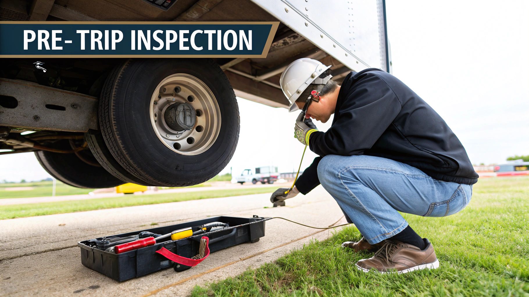
The 7 step air brake test is a critical safety sequence used by commercial drivers to ensure a vehicle's braking system is airtight and mechanically sound. It involves checking the air leakage rate, low-pressure warning signals, spring brake activation, governor cut-in/cut-out levels, and the physical functionality of the parking and service brakes.
As of 2026, the Federal Motor Carrier Safety Administration (FMCSA) and the Commercial Vehicle Safety Alliance (CVSA) continue to emphasize the air brake pre-trip inspection as the most vital component of the Commercial Driver’s License (CDL) skills test. A failure to perform these steps correctly during a roadside inspection can lead to an immediate "Out-of-Service" (OOS) order, while a failure during a CDL exam results in an automatic disqualification. This guide provides a detailed, technical walkthrough of the 7 step air brake test procedures to ensure compliance and road safety.
Prerequisites and Setup for the Air Brake Test
Before beginning the 7 step sequence, the vehicle must be properly prepared. Safety is paramount when testing a system designed to hold back 80,000 pounds of machinery. If the air system fails during testing while the vehicle is on an incline without proper securement, the truck could roll, leading to catastrophic injury or property damage.
Securing the Vehicle
The first step is to ensure the vehicle is on level ground. Once positioned, you must chock the wheels. Because the air brake test requires you to release the parking brakes (yellow and red knobs) to check for leaks and valve pops, the only thing preventing the vehicle from moving is the physical chocks.
Building Air Pressure
Start the engine and allow the air compressor to build the system pressure to the "governor cut-out" point. This is typically between 120 and 135 PSI. You will know the system is full when you hear the "sneeze" or air purge from the air dryer. Once the pressure is stabilized at the maximum level, shut off the engine but turn the battery/ignition back to the "On" or "Accessory" position. This allows the electronic gauges and warning lights to remain active without the engine noise interfering with your ability to hear potential air leaks.
Step 1: The Applied Leakage Test (Static and Applied)
The goal of the first step is to measure how much air the system loses over a specific period. Air brake systems are never 100% airtight, but the FMCSA sets strict limits on how much leakage is permissible before a vehicle is considered unsafe.
- Release the Brakes: Push in both the tractor (yellow) and trailer (red) valves. Wait for the initial drop in pressure as the air fills the lines and brake chambers.
- Stabilize the System: Once the gauges stop moving, you are ready to begin.
- Apply Constant Pressure: Firmly press and hold the service brake pedal. Do not "pump" the brakes; hold a steady, heavy pressure.
- Timing the Leak: Using a watch or a clock with a second hand, time the system for 60 seconds.
The Passing Standards:
- Straight Truck/Bus: Must not lose more than 3 PSI in one minute.
- Combination Vehicle (Tractor-Trailer): Must not lose more than 4 PSI in one minute.
If the gauge drops more than these limits, the vehicle has a significant leak in the service line, brake chambers, or diaphragms and must be repaired before operation.
Step 2: Low Air Warning Device Test
This step ensures that the driver will receive an adequate warning if air pressure drops to a dangerous level while driving. If the air pressure falls too low, the brakes will eventually lock up (the spring brakes will engage), which can be deadly at highway speeds.
With the engine off and the ignition on, begin "fanning" the brake pedal. Fanning involves pressing and releasing the brake pedal repeatedly to bleed air out of the system. Watch the primary and secondary air gauges closely.
The Low Air Warning light and buzzer must activate before the pressure drops below 55 PSI. Most modern trucks are calibrated to trigger this warning at approximately 60 PSI. If the light and buzzer do not activate by the time the gauge hits 55 PSI, the warning sensor is faulty. This is a critical failure because a driver might not realize they are losing air until the brakes suddenly lock.
Step 3: The Pop-Out Test (Emergency Spring Brake Activation)
This is the "emergency" fail-safe of the air brake system. When air pressure drops so low that the system can no longer keep the powerful springs inside the brake chambers compressed, those springs will release and apply the brakes automatically.
Continue fanning the brake pedal to further reduce the air pressure. You are watching the Tractor Protection Valve (Yellow) and the Trailer Supply Valve (Red). As the pressure continues to drop, usually between 20 and 45 PSI, both valves should "pop out" from the dashboard to the "applied" position.
This indicates that the emergency system has engaged. If the valves do not pop out by the time the pressure hits 20 PSI, the tractor protection valve or the spring brake priority system is malfunctioning. In a real-world scenario, this failure could mean the vehicle has no way to stop once the air is gone.
Step 4: Air Compressor Governor Cut-in and Cut-out
Now that you have drained the air, you must verify that the compressor can recover the pressure and that the governor correctly manages the compressor's cycle.
- Restart the Engine: Start the truck and observe the gauges.
- Check the Recovery Rate: At a fast idle (around 1,200 RPM), the pressure should rise from 85 PSI to 100 PSI within 45 seconds in a dual-air system.
- Identify Cut-out: Continue building pressure until the governor "cuts out." This is the point where the compressor stops pumping air. As of 2026, the standard cut-out is between 120 and 135 PSI. You will hear the air dryer purge.
- Identify Cut-in: With the engine running, pump the brakes to reduce pressure. The governor should "cut in" (start the compressor again) when the pressure drops by about 20-25 PSI from the cut-out point, but no lower than 100 PSI.
The governor is the "brain" of the air system. If it fails to cut out, the system could over-pressurize and blow out lines. If it fails to cut in, the system will eventually run out of air.
Step 5: Parking Brake Test
The parking brake test verifies that the mechanical force of the spring brakes is sufficient to hold the vehicle in place against the engine's torque.
- Isolate the Tractor: Ensure the trailer brakes (red knob) are pushed in (released) and the tractor brakes (yellow knob) are pulled out (engaged).
- Test the Hold: Put the vehicle in a low gear and gently tug against the parking brake by releasing the clutch slightly (or shifting into drive and giving it a small amount of gas).
- Requirement: The tractor should not move. If the truck rolls forward or backward, the parking brakes are out of adjustment or the brake linings are worn beyond safety limits.
Step 6: Trailer Brake Test
This step is specific to combination vehicles and ensures that the trailer’s braking system is functioning independently of the tractor.
- Isolate the Trailer: Push the tractor brake (yellow knob) in and pull the trailer brake (red knob) out.
- Test the Hold: Again, put the vehicle in a low gear and gently tug against the trailer brakes.
- Alternative (Hand Valve): You can also test this by releasing both dashboard valves and pulling down the trailer hand valve (the "trolley bar") while gently tugging.
- Requirement: The trailer should hold the entire unit in place. If the trailer moves, it indicates a failure in the trailer’s emergency brakes or a disconnection in the air lines.
Step 7: Service Brake Movement Test
The final step tests the actual "foot brake" and the steering geometry during braking. This is the only part of the test that requires the vehicle to be in motion.
- Release All Brakes: Push in both the yellow and red knobs.
- Move Forward: Drive forward at a very low speed (approximately 5 MPH).
- Apply Service Brake: Press the brake pedal firmly.
- Observe Response: The vehicle should come to a smooth, complete stop.
- Check for Pulling: Note if the steering wheel pulls to the left or right. A pull indicates that the brakes on one side are grabbing harder than the other, or that there is a mechanical issue with the S-cam, slack adjusters, or brake drums/discs.
| Test Component | Required Pressure/Time | Success Criteria |
|---|---|---|
| Applied Leakage (Combo) | 4 PSI / 1 Minute | No more than 4 PSI drop |
| Applied Leakage (Straight) | 3 PSI / 1 Minute | No more than 3 PSI drop |
| Low Air Warning | Activate at $\ge$ 55 PSI | Light and Buzzer must activate |
| Spring Brake Pop-out | 20 - 45 PSI | Both valves must pop out |
| Governor Cut-out | 120 - 135 PSI | Compressor stops pumping |
| Governor Cut-in | $\ge$ 100 PSI | Compressor starts pumping |
| Air Build-up Rate | 85 to 100 PSI in 45 sec | Rapid pressure recovery |
Common Mistakes and Troubleshooting
Performing the 7 step air brake test requires precision. Even experienced drivers in 2026 occasionally fail roadside inspections due to simple procedural errors.
Failure to Secure the Vehicle
The most common and dangerous mistake is failing to chock the wheels. When you release the parking brakes in Step 1, the vehicle is essentially in "neutral" regarding its braking system. If the ground is not perfectly level, the truck will roll. In a CDL exam, failing to mention or perform wheel chocking is an automatic failure.
Pumping the Brakes During the Leakage Test
During Step 1 (Applied Leakage), some drivers mistakenly pump the pedal. This exhausts air and gives a false reading of a massive leak. You must maintain steady, constant pressure. Any movement of the foot will fluctuate the gauge and invalidate the test.
Ignoring the Ignition Position
For the Low Air Warning and Pop-out tests, the engine must be off, but the electrical system must be on. If the key is in the "Off" position, the buzzer and light will not activate, leading the driver to believe the system is broken when, in fact, it simply has no power.
Misinterpreting Gauge Lag
Air gauges are mechanical-electronic hybrids and can sometimes lag. When you first press the brake pedal for the Applied Leakage test, the needle will drop immediately. This is not the "leak." This is the air filling the service lines. You must wait for the needle to stabilize before you start your one-minute timer.
Regulatory Compliance and the CVSA
The CVSA (Commercial Vehicle Safety Alliance) conducts "Brake Safety Week" annually. During these events, inspectors focus specifically on the components checked during the 7 step test.
According to 49 CFR § 393.51, every bus, truck, and truck-tractor must be equipped with a signal that provides a warning to the driver when the air pressure in the service brake system is below a fixed level. Furthermore, 49 CFR § 396.11 requires drivers to perform daily inspections. The 7 step test is the standard by which these legal requirements are met.
If a driver identifies a failure during any of these steps, the vehicle is legally not roadworthy. Driving with a known air brake deficiency can lead to "willful negligence" charges in the event of an accident, which carries severe legal and financial consequences for both the driver and the carrier.
Frequently Asked Questions
What happens if only one valve pops out during the Pop-out test?
Both the yellow (tractor) and red (trailer) valves should pop out. If only one pops, it usually means the tractor protection valve is not communicating correctly with the trailer supply system. This is a safety failure because it implies that a pressure drop in the tractor might not automatically protect the trailer's air supply.
Can I perform the 7 step test while the engine is running?
Only specific parts. The Applied Leakage, Low Air Warning, and Pop-out tests (Steps 1, 2, and 3) must be done with the engine off to ensure the compressor isn't masking a leak. The Governor, Parking, Trailer, and Service Brake tests (Steps 4, 5, 6, and 7) require the engine to be running to build pressure or move the vehicle.
Is the 7 step test the same for disc brakes and drum brakes?
Yes. While the mechanical application at the wheel end differs (calipers vs. S-cams), the pneumatic (air) system that triggers them is identical. The pressure thresholds and leakage rates remain the same regardless of the friction hardware used.
Why is 55 PSI the magic number for the low air warning?
The FMCSA designated 55 PSI because it provides a "buffer" zone. Most spring brakes will not begin to engage until the pressure drops below 45 PSI. By alerting the driver at 55 PSI, the regulations ensure the driver has enough remaining air to controlledly pull over to the shoulder before the brakes lock up and the vehicle becomes unmovable.
How often should I perform the 7 step air brake test?
Legally, it must be part of your Pre-Trip Inspection every day you operate the vehicle. Many safety-conscious drivers also perform a "short version" (checking the gauges and a quick service brake tug) every time they pick up a new trailer to ensure the glad-hands are sealed correctly.
Summary of Next Actions
To maintain compliance in 2026, ensure that your air brake testing is documented in your Driver Vehicle Inspection Report (DVIR). If you are a student preparing for the CDL, practice the "L-A-B" mnemonic: Leaks (Step 1), Alarm (Step 2), and Buttons (Step 3). Mastering these three "engine-off" steps is the most common hurdle for new drivers. For fleet managers, regular audits of driver inspection techniques can prevent costly OOS violations and, more importantly, ensure that every vehicle on the road can stop safely in an emergency.