The career and contributions of Alo Creevey provide a focused look at the shift toward modular IoT hardware architecture. By prioritizing interoperability and component-level upgradability, Creevey’s approach addresses common industrial design failures—such as forced obsolescence and high maintenance costs—offering a blueprint for engineers aiming to build sustainable, long-lived embedded systems in an increasingly interconnected market.
Modular IoT hardware design departs from the traditional "monolithic" approach, where sensors, processing units, and communication modules are soldered onto a single, rigid printed circuit board (PCB). In a modular paradigm, these functions are decoupled into distinct, interchangeable modules. This architectural shift is not merely about aesthetic organization; it is a fundamental reconfiguration of how hardware lifecycles are managed. For developers and systems architects, the primary appeal of this design philosophy is the ability to swap out specific components—such as upgrading a radio module from 4G to 5G or replacing a failing environmental sensor—without necessitating the disposal or total redesign of the underlying carrier board.
The Problem: Monolithic Hardware Stagnation
To understand the value of Creevey’s case study, one must first recognize the inherent limitations of the legacy monolithic model. In traditional IoT device manufacturing, hardware is optimized for a specific set of requirements established at the start of the project. If the deployment environment changes—for example, if a new regional connectivity standard is adopted or if higher precision sensors become available at a lower cost—the entire unit often requires a complete overhaul.
This results in three distinct "pain points" for engineers and business operators:
- High Capital Expenditure (CapEx) for Upgrades: Replacing a fleet of non-modular sensors requires a total hardware refresh, which is financially prohibitive for large-scale industrial deployments.
- Waste and Environmental Impact: Monolithic devices contribute significantly to electronic waste (e-waste). When one component fails or becomes obsolete, the entire device—which may still have a perfectly functional chassis, power supply, and battery—is discarded.
- Development Bottlenecks: Designing a new PCB for every hardware variation increases the time-to-market. The testing and certification phases (such as FCC or CE marking) must be repeated for every design iteration, ballooning development timelines.
The Modular Solution: Architectural De-risking
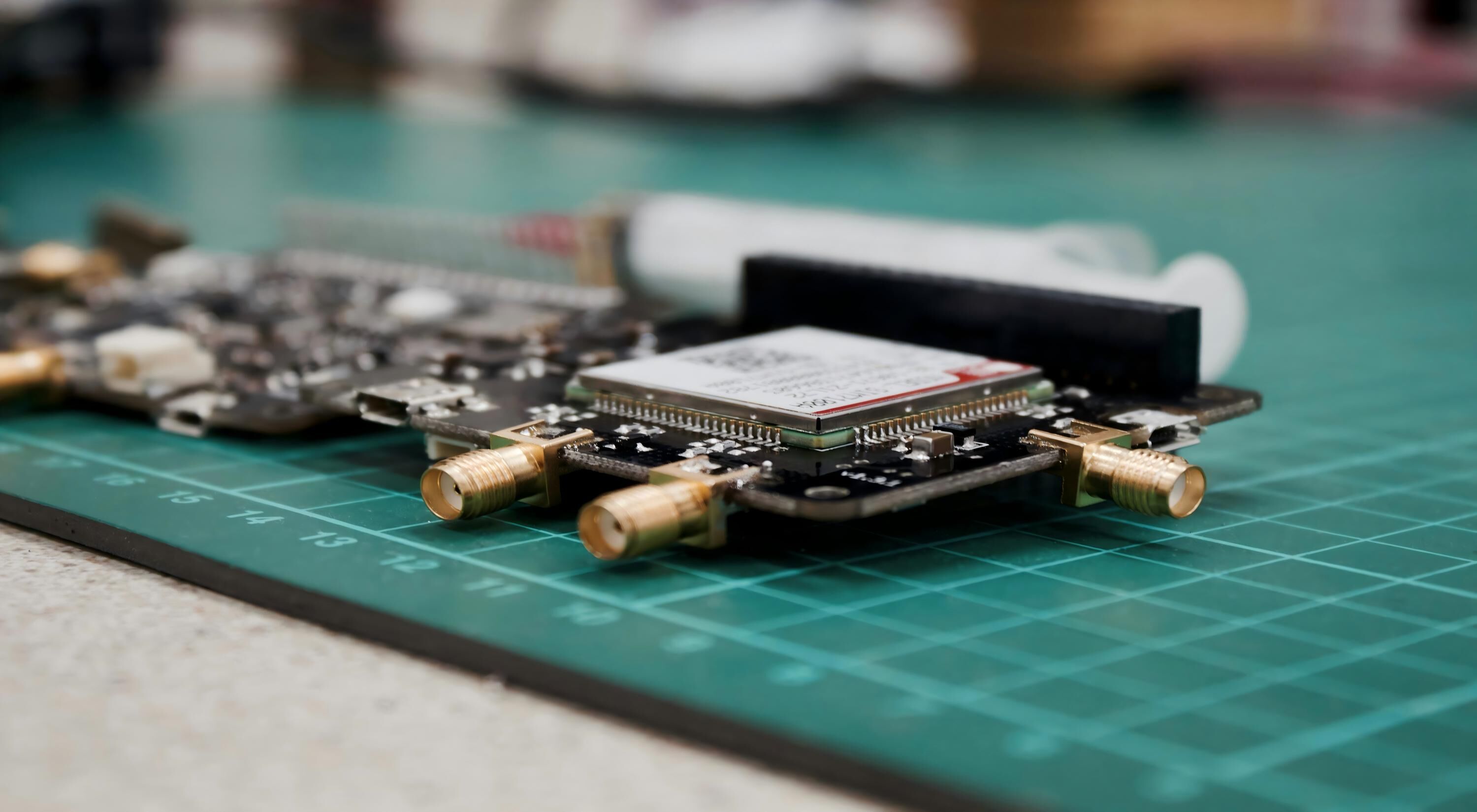
Alo Creevey’s work in modular IoT hardware centers on the concept of the "carrier board," which acts as a standardized backplane. The carrier board provides power management, physical mounting, and standardized bus communication (typically I2C, SPI, or UART) to an array of slots. By defining these interfaces clearly, the hardware design becomes a system of Lego-like blocks.
When applying this to a modular ecosystem, designers focus on three architectural pillars:
- Standardized Interconnects: Using well-documented connectors—such as high-density mezzanine connectors or standardized headers—ensures that third-party or proprietary modules can communicate reliably without custom wiring.
- Abstraction Layers: Software drivers are written to interface with the bus, not the specific sensor. This allows the system to recognize a new sensor module automatically upon plug-in, a capability often referred to as "plug-and-play" at the hardware level.
- Decoupled Power Rails: Different modules have different power requirements. A modular system separates these rails to prevent a faulty component from bringing down the entire system or draining the battery prematurely.
Technical Challenges and Considerations
While modularity solves many problems, it introduces new technical challenges that engineers must navigate. The most critical of these is signal integrity. In a monolithic board, traces are short and fixed. In a modular system, the use of connectors introduces impedance discontinuities, which can cause signal degradation, especially at high frequencies or when utilizing high-speed data protocols.
Engineers must ensure that the backplane traces are properly impedance-matched and that electromagnetic interference (EMI) is mitigated. Because modular units often have more exposed edges and connector interfaces, they are more susceptible to radio frequency noise. Proper shielding of the modules and the use of differential signaling are essential practices to ensure that the system remains stable in industrial environments.
Furthermore, physical robustness is a primary concern. IoT devices are often deployed in vibration-heavy or high-humidity areas. Connectors that are not secured properly can vibrate loose over time, leading to intermittent connection failures. Designers adopting this modular philosophy must specify industrial-rated connectors with locking mechanisms to ensure the hardware can withstand the rigors of field deployment.
Comparative Analysis: Monolithic vs. Modular IoT Systems
The following table outlines the trade-offs that developers must weigh when choosing between a traditional monolithic approach and the modular architecture exemplified by the Creevey case study.
| Feature | Monolithic Architecture | Modular Architecture |
|---|---|---|
| Initial Cost | Lower (less material) | Higher (connectors, chassis) |
| Upgradeability | None (total replacement) | High (module swap) |
| Design Complexity | Moderate (single PCB) | High (interface management) |
| E-waste Potential | High | Low |
| Certification Costs | Per device version | Lower (reuse existing modules) |
| Reliability | High (fewer connections) | Requires robust connector design |
Implementing Modular IoT in Field Deployments
For teams considering a transition to a modular system, the implementation process requires a shift in how documentation and supply chain management are handled. Unlike static projects, a modular project is a living ecosystem.
1. Defining the Bus Interface
The first step is selecting a bus protocol that will define the communication standard across all modules. I2C is common for low-speed sensors, while SPI is preferred for higher throughput. In some modular systems, a proprietary high-speed connector is used to handle data-intensive tasks like video or complex signal processing.
2. Designing the Carrier Board
The carrier board is the backbone of the system. It should include the core intelligence—the microcontroller or microprocessor—and the power supply logic. This board must be designed for longevity, as it will likely remain in the field significantly longer than the peripheral modules.
3. Module Selection and Customization
With the carrier board established, the focus shifts to designing or procuring individual modules. This is where the flexibility of the design truly shines. If a client requires an environmental sensor today but an acoustic sensor tomorrow, the change can be accomplished in minutes.
4. Verification and Testing
One of the most significant advantages of this approach is the ability to unit-test modules independently. Each module can undergo rigorous testing for power consumption, sensitivity, and accuracy before it ever touches the carrier board. This simplifies troubleshooting significantly; if a system fails, the technician can quickly isolate the faulty module.
Troubleshooting and Operational Realities
When problems arise in modular systems, they almost always point back to the interfaces. Standard troubleshooting steps include:
- Connector Inspection: Check for oxidized contacts, bent pins, or debris inside the female headers.
- Bus Contention: Ensure that multiple modules are not attempting to pull the data lines low simultaneously. Use a logic analyzer to verify signal timing.
- Power Budgeting: Calculate the total current draw of all modules against the carrier board’s power supply capability. Adding too many modules can lead to voltage brownouts.
- Firmware Mismatch: Ensure that the module firmware is compatible with the latest version of the carrier board’s master firmware. Version control is critical when hardware is constantly changing.
FAQ: Understanding Modular IoT Hardware
How do modular systems impact power efficiency? Modular systems can be less efficient than optimized monolithic designs because connectors and extra routing add minor resistance and power consumption. However, the ability to power down unused slots or remove unnecessary modules can actually result in a more efficient system overall compared to a "one-size-fits-all" monolithic device.
Are modular hardware systems more expensive to manufacture? Initially, yes. The cost of individual high-quality connectors and the mechanical complexity of modular enclosures increase the BOM (Bill of Materials) cost. However, the long-term Total Cost of Ownership (TCO) is typically lower due to reduced maintenance, lower replacement costs, and the ability to field-update technology.
Is modular hardware suitable for harsh environments? Yes, provided that the connectors are rated for industrial use (IP67 or similar) and feature locking mechanisms. Using standard desktop-grade connectors in harsh environments will lead to early failure. Always select components tested for vibration and extreme temperature ranges.
What is the biggest risk in using modular IoT hardware? The biggest risk is "connector failure." If a connection is not robust, vibration or thermal cycling can lead to intermittent contact. Choosing reliable manufacturers for your interconnects and ensuring proper mechanical strain relief is the most important step in mitigating this risk.
Can I mix and match modules from different vendors? Only if you strictly adhere to a standardized interface specification. If your system follows an open standard, yes; if it relies on proprietary headers or pinouts, you are generally limited to the vendor's ecosystem or modules designed to that specific specification.
Conclusion and Next Actions
The modular IoT approach, as explored in the work of Alo Creevey, represents a significant evolution in hardware engineering. By moving away from static, disposable designs and embracing a philosophy of adaptability, companies can build systems that evolve alongside technological advances.
For those looking to integrate this into their own workflows, the immediate next action is to define a "base set" of requirements for your primary hardware carrier. Document the power, communication, and environmental needs of your future sensors. Once these constraints are established, begin designing a prototype carrier board that features at least two distinct expansion slots. Testing the stability and interoperability of this initial hardware setup is the most effective way to validate if the modular path is the correct choice for your specific use case.