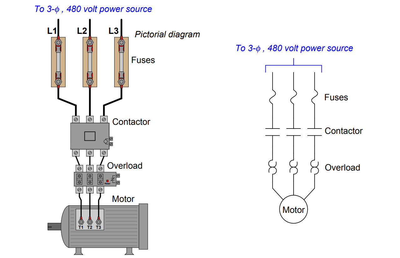
A three-phase motor overload occurs when a motor draws more current than its rated capacity for a sustained period, generating excessive heat that degrades winding insulation and can cause catastrophic failure if protective devices fail to interrupt the circuit.
Introduction to Three-Phase Induction Motors and Thermal Stress
Three-phase alternating current (AC) induction motors serve as the industrial workhorses of modern manufacturing, HVAC systems, municipal water treatment plants, and large-scale commercial facilities. Their robust construction, self-starting capabilities, and high operational efficiency make them indispensable. However, even the most rugged industrial motor remains vulnerable to thermal stress. Understanding what happens during a three-phase motor overload is essential for electrical technicians, plant managers, and maintenance personnel who must balance uptime against equipment longevity.
When an electrical motor operates under normal conditions, it converts electrical energy into mechanical energy with a predictable thermal footprint. The cooling mechanisms—whether internal fans, external fins, or forced-air blowers—dissipate the heat generated by electrical resistance in the windings and mechanical friction in the bearings. An overload disrupts this delicate thermal equilibrium. When mechanical resistance, voltage fluctuations, or phase anomalies force the motor to work harder, current draw increases. Because heat generation in a conductor increases with the square of the current ($I^2R$ losses), even a seemingly modest increase in current leads to a rapid, exponential rise in winding temperature.
Defining a Three-Phase Motor Overload
To properly diagnose and prevent motor failure, it is vital to distinguish between a motor overload and a short circuit. While both involve excessive current, their characteristics, magnitudes, and protective requirements differ fundamentally.
Overload vs. Short Circuit
An overload is an overcurrent condition that occurs within a normal circuit path. It is typically modest in scale—ranging from 100% to several hundred percent of the motor’s full-load amperage (FLA)—and develops because the motor is mechanically driven beyond its rated capacity or is receiving abnormal voltage. Crucially, an overload is a sustained condition. If left uninterrupted, the heat generated will eventually melt the varnish insulation surrounding the copper windings, causing a permanent short circuit.
A short circuit (or ground fault), by contrast, is an abnormal connection of very low resistance between phase conductors or between a phase conductor and ground. Short-circuit currents can reach thousands of amperes instantaneously. Protective devices like fuses and instantaneous magnetic circuit breakers must clear short circuits within milliseconds to prevent explosions and severe arc flash hazards. Overloads, however, require time-delay protection that allows the motor to draw high inrush current during startup without tripping, while still stepping in if that high current persists long enough to cause thermal damage.
The Role of Full-Load Amperage (FLA)
Every three-phase motor features a nameplate detailing its electrical specifications. Among the most critical data points is the Full-Load Amperage (FLA). FLA represents the current in amperes that the motor draws when operating at its rated horsepower, voltage, and frequency under a fully loaded condition.
Motor overloads are calculated relative to this FLA rating. If a motor has an FLA of 20 amperes and a service factor of 1.15, it can safely handle up to 23 amperes under specific conditions, but sustained operation beyond that threshold initiates thermal degradation. Protective devices are calibrated using this FLA figure to ensure they trip before winding temperatures exceed the insulation class limit (such as Class B, F, or H).
Primary Causes of Three-Phase Motor Overloads
Motor overloads rarely happen without an underlying mechanical or electrical root cause. Identifying why an overload occurs is just as important as resetting the protective relay. The causes can be broadly categorized into mechanical burdens, electrical supply abnormalities, and environmental factors.
Mechanical Causes
- Driven Load Binding: Bearings in pumps, gearboxes, or conveyor systems can seize, dry out, or fail. This increases the torque required to turn the shaft, forcing the motor to draw more current to maintain speed.
- Misalignment and Coupling Issues: If the motor shaft and the driven equipment shaft are misaligned, mechanical stress increases friction, manifesting as an artificial overload on the motor windings.
- Material Jamming: In industrial processing, foreign objects jammed in an auger, crusher, or fan housing can abruptly stall or heavily load the motor.
- Excessive Cycling: Starting a three-phase motor too frequently generates massive heat spikes during the high-amperage starting phase (inrush current). If the motor cannot shed this heat between starts, cumulative thermal overload occurs.
Electrical Supply Causes
- Voltage Unbalance: Three-phase systems rely on balanced voltages across all three phases ($L_1$, $L_2$, $L_3$). According to NEMA standards, a voltage unbalance as small as 2% can cause a current unbalance of 6% to 10% in the motor windings. This current unbalance creates severe localized heating in one or more phases while other parts of the motor remain underloaded.
- Under-Voltage / Over-Voltage: Operating a motor below its rated voltage forces it to draw higher current to produce the same electromagnetic torque (known as "slipping" harder). Conversely, extreme over-voltage can saturate the magnetic core, increasing iron losses and heating.
- Single-Phasing: If one of the three supply lines is lost due to a blown fuse, a broken wire, or a loose terminal connection, the motor transitions into single-phase operation. To maintain its load with only two active phases, the motor draws massive current through those remaining windings, often burning them out within minutes if unaddressed.
Environmental Factors
- High Ambient Temperatures: Motors are rated for specific maximum ambient temperatures (typically 40°C / 104°F). If a motor is installed in a poorly ventilated enclosure, a boiler room, or direct sunlight, its ability to dissipate internal heat is severely compromised.
- Altitude Derating: At high altitudes, air density decreases, reducing the cooling efficiency of ambient air over the motor frame. Motors operated above 3,300 feet (1,000 meters) often require derating or specialized cooling.
- Blocked Ventilation Paths: Accumulated dust, dirt, grease, or debris on the motor cooling fins act as an insulating blanket, trapping heat inside the frame.
How Overload Protection Devices Work
Because humans cannot monitor motor winding temperatures in real time, electrical engineers use specialized protective devices integrated into motor control centers (MCCs) and starter panels. These devices monitor current draw and interrupt the control circuit when thresholds are breached.
Thermal Overload Relays (Bimetallic and Melting Alloy)
Traditional and widely used thermal overload relays rely on physical expansion or phase change caused by heat.
- Bimetallic Strips: Inside the relay, current flows through or around a heating element that warms a bimetallic strip made of two bonded metals with different expansion coefficients. As the strip heats up due to excess current, it bends, eventually tripping a mechanical latch that opens the control circuit and shuts down the contactor.
- Melting Alloy ("Solder Pot"): These relays use a eutectic alloy (a metal mixture with a precise melting point) enclosed in a small gear-driven ratchet wheel. When sustained overload current generates excess heat in the surrounding heater coil, the alloy melts, releasing the ratchet and tripping the contacts. Once the alloy cools and solidifies, the relay can be reset.
Electronic and Microprocessor-Based Overload Relays
Modern industrial installations increasingly utilize electronic overload relays. These devices use current transformers (CTs) to measure actual phase currents continuously.
- Inverse-Time Characteristic Curves: Electronic relays emulate the thermal memory of the motor. They calculate $I^2t$ (current squared multiplied by time) to mimic how winding insulation heats up and cools down. A severe overload trips the relay rapidly; a minor overload allows a longer grace period before tripping.
- Phase Loss and Unbalance Protection: Unlike mechanical relays that only monitor total current magnitude, microprocessor relays monitor phase-to-phase current symmetry. If an unbalance exceeds a programmed threshold (e.g., 5%), the relay trips immediately to protect against single-phasing.
| Overload Relay Type | Primary Mechanism | Advantages | Limitations |
|---|---|---|---|
| Bimetallic Thermal | Differential metal expansion via heater coils | Cost-effective, reliable, adjustable trip current | Affected by ambient panel temperature |
| Melting Alloy (Solder Pot) | Eutectic alloy melting point release | Highly repeatable trip characteristics | Requires heater element replacement if damaged; non-adjustable |
| Electronic / Microprocessor | Digital current sensing & $I^2t$ modeling | Precise protection, phase-loss detection, thermal memory | Higher initial cost, requires control power in some models |
Troubleshooting a Tripped Three-Phase Motor Overload
When a three-phase motor overload relay trips, it signals that the safety system has prevented an imminent motor burnout. Maintenance technicians must systematically investigate the root cause rather than simply resetting the relay and restarting the equipment.
Step 1: Safety First (Lockout/Tagout)
Before opening any electrical enclosure or touching motor terminals, perform proper Lockout/Tagout (LOTO) procedures. Verify zero energy state using a calibrated multimeter rated for the appropriate category (e.g., CAT III or CAT IV).
Step 2: Inspect the Physical Environment and Mechanical Load
- Check the motor frame temperature by touch (carefully) or with an infrared thermometer. Is the motor excessively hot?
- Verify that cooling fans are operating, ventilation grills are clean, and ambient temperatures are within specification.
- Manually rotate the driven equipment (if safe and accessible) to check for binding, seized bearings, or mechanical obstructions.
Step 3: Check Electrical Connections and Supply Voltage
- Inspect all terminal connections in the motor junction box and the motor starter panel for looseness, corrosion, or discoloration (signs of arcing).
- Measure the line-to-line voltages across all three phases while the system is energized (if troubleshooting live requires specialized safety gear and NFPA 70E compliance). Ensure voltage unbalance is below 1%.
- Check for blown fuses upstream that might indicate an intermittent single-phasing event.
Step 4: Measure Operating Current (Amperage)
Once the motor is reset and running under normal load, use a clamp-on digital multimeter to measure the current on all three phases ($L_1$, $L_2$, and $L_3$).
- Compare the measured values against the motor nameplate FLA.
- Verify that current draw is balanced across all three phases. If one phase draws significantly more or less current than the others, an electrical supply or winding issue exists.
Step 5: Evaluate the Overload Relay Setting
Verify that the overload relay dial is correctly set to match the motor’s full-load amperage (FLA) as listed on the nameplate. If a motor was rewound or replaced with a different specification, an unadjusted overload setting will cause nuisance tripping or leave the motor unprotected.
Best Practices for Preventing Three-Phase Overloads
Proactive maintenance programs dramatically reduce the frequency of motor overloads and extend the operational lifecycle of electrical assets.
- Implement Infrared Thermography: Use thermal imaging cameras during routine electrical audits to identify high-resistance connections, overloaded phases, and failing bearings before they trigger a system trip.
- Monitor Power Quality: Install power quality meters to track voltage sags, surges, and phase unbalances over time, allowing facility teams to address utility supply issues before they damage motors.
- Maintain Lubrication Schedules: Follow original equipment manufacturer (OEM) guidelines for lubricating motor and driven-equipment bearings to prevent mechanical binding and increased friction torque.
- Keep Windings Clean: Regularly clean dust, dirt, and chemical residue from motor cooling fins and frames to ensure optimal heat dissipation.
Conclusion
A three-phase motor overload is a critical warning sign of thermal stress driven by mechanical resistance, electrical unbalance, or environmental factors. While protective relays successfully prevent catastrophic winding destruction by interrupting the circuit, treating the symptom by simply resetting the relay fails to solve the underlying problem. By combining rigorous diagnostic troubleshooting—examining FLA, phase balance, and mechanical load—with proactive thermal maintenance, facility teams can ensure long-term reliability and operational safety across all industrial motor applications.