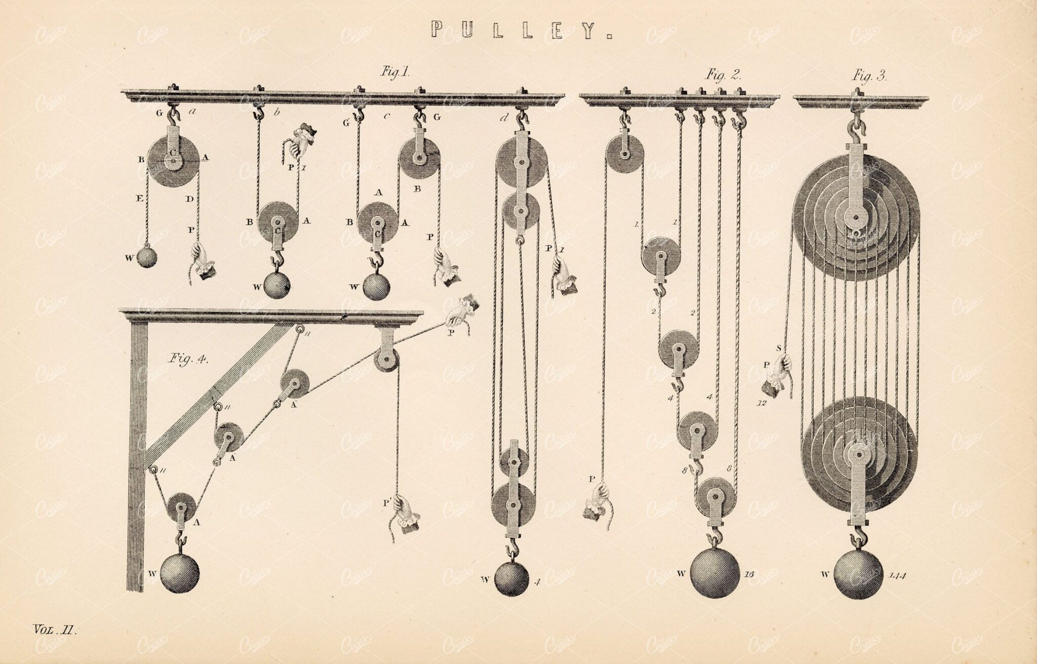
Properly aligning pulleys in mechanical systems involves ensuring that the rotational axes of the driving and driven shafts are parallel and that the pulley grooves reside in the exact same plane. This process eliminates unnecessary friction, reduces vibration, and prevents premature wear of belts and bearings, ultimately extending the operational lifespan of industrial machinery and power transmission components.
The Critical Role of Alignment in Modern Power Transmission
As of 2026, the industrial landscape continues to prioritize energy efficiency and equipment reliability. In any belt-driven system, whether it utilizes V-belts, synchronous belts, or ribbed belts, the precision of pulley alignment remains the most influential factor in mechanical health. When pulleys are misaligned, the belt does not enter the groove smoothly. Instead, it "scuffs" or "climbs" the sidewalls of the sheave, converting valuable kinetic energy into waste heat and noise.
In high-torque or high-speed applications, even a fraction of a degree of misalignment can lead to catastrophic failure. Misalignment introduces transverse forces—loads that act perpendicular to the direction of travel. These forces pull the shafts toward one another unevenly, putting an immense strain on the internal rolling elements of the bearings. By mastering the art of pulley alignment, maintenance teams can reduce downtime, lower replacement costs, and significantly improve the carbon footprint of their facility by reducing parasitic energy losses.
Understanding the Types of Pulley Misalignment
Before attempting to correct an issue, a technician must identify the specific nature of the misalignment. Most mechanical systems suffer from a combination of three distinct types of errors.
1. Parallel Misalignment (Offset)
Parallel misalignment, often called offset, occurs when the shafts are perfectly parallel to each other, but the pulleys are located at different positions along those shafts. In this scenario, the belt is forced to travel in a "dog-leg" or "Z" pattern. While the belt stays seated, it experiences constant lateral stress, leading to edge wear and uneven heating.
2. Horizontal Angular Misalignment
This occurs when the shafts are in the same horizontal plane but are not parallel. They are effectively "toed in" or "toed out" relative to one another. This is one of the most common issues found during initial motor installations where the mounting bolts allow for slight rotation of the motor frame.
3. Vertical Angular Misalignment (Twist)
Vertical angularity happens when one shaft is tilted at a different angle relative to the floor or the baseplate than the other. This is frequently caused by an uneven mounting surface or a "soft foot" condition, where one corner of the motor or driven component is not making solid contact with the base, causing the shaft to tilt when the mounting bolts are torqued down.
Essential Tools for Precise Alignment
The methods used to align pulleys have evolved, but the underlying principles remain the same. The choice of tool usually depends on the required precision and the distance between the shafts.
- Straightedges and Strings: The traditional approach involves pressing a long, rigid straightedge against the outer faces of the pulleys. While cost-effective, this method is prone to human error, such as "parallax error," where the technician views the gap from an angle. Strings are often used for longer spans, though they are susceptible to sagging and wind interference.
- Laser Alignment Systems: Modern laser tools are the gold standard in 2026. These devices typically use a laser emitter mounted on one pulley and a target (or reflector) on the other. They provide real-time feedback on both angularity and offset simultaneously. Some advanced units now integrate with IoT maintenance platforms to log alignment data automatically.
- Vernier Calipers and Micrometers: These are used to ensure the pulleys themselves are of the correct dimensions and that the shafts are not tapered.
- Dial Indicators: While more common in shaft-to-shaft coupling alignment, dial indicators are used in pulley systems to check for "runout"—the degree to which a pulley wobbles or is off-center during rotation.
Pre-Alignment Inspection and Safety Requirements
Alignment should never be performed on a system that is fundamentally flawed. Before reaching for the laser, a thorough inspection of the mechanical components is required.
- Lockout/Tagout (LOTO): This is non-negotiable. Ensure the power source is disconnected and locked according to OSHA or local safety standards to prevent accidental startup.
- Inspect Sheave Grooves: Check for "ridging" or "dishing" in the pulley grooves. If the sidewalls are worn or concave, the belt will slip regardless of how well the system is aligned. Use a sheave gauge to verify the profile.
- Check Shaft Straightness: A bent shaft will cause a pulley to "wobble," creating a dynamic misalignment that cannot be corrected through standard positioning.
- Verify Bearing Condition: Excessive play in the bearings will allow the shafts to move under load. If the bearings are failing, the alignment will shift as soon as the motor starts.
- Clean All Surfaces: Remove rust, paint, or debris from the shaft and the pulley bores. Any contamination here can cause the pulley to sit "cocked" on the shaft.
The Step-by-Step Pulley Alignment Process
Achieving precision requires a methodical approach. Follow these steps to ensure the driving and driven components are perfectly synchronized.
Step 1: Initial Mounting and Leveling
Mount the pulleys on their respective shafts and tighten the bushings (such as Taper-Lock or QD bushings) to the manufacturer’s specified torque. Use a precision level to ensure the baseplate is horizontal. If the base is twisted, it becomes nearly impossible to eliminate vertical angularity.
Step 2: Correcting Soft Foot
Before checking alignment, ensure the motor sits flat. Loosen all mounting bolts and see if any foot has a gap beneath it. Use feeler gauges to measure the gap and fill it with stainless steel shims. A "soft foot" will distort the motor frame when tightened, pulling the shaft out of alignment.
Step 3: Measuring Initial Misalignment
Place your alignment tool (laser or straightedge) across the faces of the pulleys. If using a laser, the beam will indicate exactly how far off the target is in terms of both offset and angle. Record these initial values to track your progress.
Step 4: Adjusting Vertical Angularity
Vertical angles are adjusted by adding or removing shims under the front or rear feet of the motor. For example, if the motor shaft is tilted "up," you would add shims to the rear feet to level it out.
Step 5: Adjusting Horizontal Angularity and Offset
Horizontal adjustments are made by physically moving the motor side-to-side on the baseplate. Most industrial motor bases include "jack bolts" or "pusher bolts" that allow for micro-adjustments. Use these to rotate the motor until the horizontal angularity is zeroed out, then slide the motor laterally to correct the parallel offset.
Step 6: Final Verification
Once the tool indicates the pulleys are aligned, tighten the mounting bolts in a "star" pattern. Re-check the alignment after tightening, as the act of torquing the bolts can sometimes pull the motor slightly out of position.
Technical Specifications and Tolerances
Alignment is rarely "perfect," but it must fall within acceptable engineering tolerances. These tolerances vary based on the type of belt and the speed of the drive.
| Belt Type | Max. Angular Misalignment | Max. Parallel Offset |
|---|---|---|
| V-Belts | 0.5 Degrees | 1/10" per foot of center distance |
| Synchronous (Timing) Belts | 0.25 Degrees | 1/16" per foot of center distance |
| High-Speed Ribbed Belts | 0.20 Degrees | 0.05" total offset |
| Long-Span Conveyors | 1.0 Degree | 1/4" total offset |
As indicated in the table, synchronous belts require much tighter tolerances than V-belts. This is because synchronous belts have teeth that must mesh perfectly with the pulley grooves; even slight misalignment will cause the belt to "climb" the flange, leading to rapid tooth shear.
Common Mistakes in Pulley Alignment
Even experienced technicians can fall into traps that compromise the longevity of the system.
- Ignoring Belt Tension: Alignment and tensioning are two sides of the same coin. A belt that is perfectly aligned but undertensioned will slip, while an overtensioned belt will pull the shafts out of alignment by deflecting them. Always re-verify alignment after the final tension is set.
- Aligning to the Pulley Face Only: This assumes the pulley face is perfectly perpendicular to the groove. On cheap or worn pulleys, the face might be slightly distorted. High-precision laser systems often align based on the grooves themselves rather than the outside face to avoid this error.
- Using Improper Shim Material: Never use "found" materials like pieces of aluminum cans or cardboard as shims. These materials compress over time, leading to a recurrence of misalignment. Use only high-quality, corrosion-resistant stainless steel shims.
- Over-reliance on Visual Inspection: The human eye cannot reliably detect a 0.5-degree angle over a short distance. Always use a dedicated tool, whether it is a precision straightedge or a digital laser.
Troubleshooting Misalignment Symptoms
If you suspect a system is out of alignment but cannot immediately take it offline for inspection, look for these "red flags" during operation:
- Excessive Heat: Use an infrared thermometer to check the temperature of the belt and pulleys. If one side of the belt is significantly hotter than the other, it indicates lateral friction from misalignment.
- Belt Chirping or Squealing: While often attributed to low tension, a consistent "chirp" as the belt enters the pulley is a classic sign of angular misalignment.
- Accumulation of Rubber Dust: A fine black powder (belt "dust") gathering beneath the drive is evidence of the belt being "shaved" by the pulley sidewalls.
- Vibration Analysis: If using vibration sensors (common in 2026 predictive maintenance suites), misalignment typically shows up as high-amplitude peaks at the 1X and 2X rotational frequencies in the axial direction.
Advancements in 2026: The Future of Alignment
In 2026, the industry has seen a shift toward "smart" power transmission. Modern pulleys are increasingly equipped with embedded sensors that can detect misalignment in real-time. These systems use internal strain gauges to measure the lateral pressure on the grooves. If the pressure exceeds a certain threshold, the system sends an alert to the maintenance team before any damage occurs.
Furthermore, augmented reality (AR) is becoming a standard tool for field technicians. By wearing AR glasses, a technician can see a digital overlay of the laser alignment data directly on the physical machinery, making it much easier to visualize which "foot" needs shimming and by exactly how much.
FAQ: Frequently Asked Questions
Can I align pulleys while the machine is running?
No. For safety reasons, pulley alignment must always be performed while the machine is completely powered down and locked out. Attempting to measure or adjust a moving belt-drive system carries a high risk of entanglement and severe injury. Furthermore, the dynamic forces of a running machine make precise measurement impossible.
How often should I check the alignment of my mechanical systems?
Alignment should be checked during initial installation, after any component replacement (belts, pulleys, or motors), and as part of a regularly scheduled preventive maintenance program—typically every six to twelve months. In critical or high-vibration environments, quarterly checks are recommended.
Does pulley diameter affect alignment tolerances?
Yes. Smaller pulleys are generally less forgiving of misalignment than larger ones. Because a smaller pulley has a tighter radius of curvature, the belt undergoes more intense internal stresses. Any misalignment in a small sheave compounds these stresses, leading to much faster belt fatigue than would occur on a larger sheave with the same angular error.
What is "runout" and how does it relate to alignment?
Runout is the measure of how much a pulley deviates from a perfect circle or a perfect plane as it rotates. Radial runout means the pulley is "off-center," while axial runout means the pulley "wobbles" side-to-side. If a pulley has significant runout, it will appear to be misaligned even if the shafts are perfectly positioned. Runout should be corrected (usually by replacing the pulley or bushing) before final alignment.
Why is laser alignment better than using a string?
Laser alignment eliminates the "human factor" of visual estimation. A laser beam does not sag, is not affected by wind, and provides a perfectly straight reference line over long distances. Most importantly, laser systems can measure both offset and angularity simultaneously, whereas a string requires multiple separate measurements that are difficult to coordinate.
Final Recommendation for Optimal System Health
For the best results in any mechanical system, transition your maintenance protocol from reactive to proactive. Invest in a high-quality laser alignment tool and ensure all technicians are trained in its use. When installing new belts, always perform a "run-in" period—operate the system for 24 to 48 hours, then re-check both the tension and the alignment. This accounts for the initial "seating" of the components and ensures the system remains in its optimal state for the long term.